Electrical load vs capacity: A practical comparison for safe sizing
A technical comparison of electrical load vs capacity, covering definitions, sizing methods, margins, and practical steps for engineers and technicians to design safer systems.

Electrical load vs capacity describes the relationship between the actual demand placed on an electrical system (load) and the system's maximum allowable capability (capacity). Understanding this distinction helps engineers size equipment, select protective devices, and prevent overheating or nuisance trips, especially in multi-load scenarios. In practice, staying within capacity with a healthy margin keeps systems safe and reliable.
Understanding electrical load vs capacity
Electrical load vs capacity is a foundational concept in electrical engineering and facilities management. The term describes the balance (or imbalance) between what a system is actively drawing from its sources — the electrical load — and what the system is designed to safely handle — its capacity. Practically, load refers to the sum of power being consumed by all devices, motors, lighting, and appliances connected to the circuit, while capacity refers to the maximum current or power that cables, panels, and protective devices are designed to carry without overheating or failing. According to Load Capacity, recognizing this distinction reduces heat buildup and limits the risk of unexpected trips or insulation damage. For engineers, the challenge is to quantify the real-world load accurately and compare it against reliable capacity ratings, all while accounting for diversity, inrush, and continuous duty factors. In the context of electrical load vs capacity, margins matter because real systems rarely run exactly at rated limits; however, misalignment can still lead to hazard and downtime, particularly in aging installations or high-peak environments.
Key concepts: real vs apparent load and rated capacity
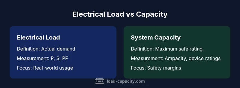
To understand electrical load vs capacity, you must distinguish real power (P, measured in watts), apparent power (S, measured in volt-amperes), and reactive power (Q, VARs). Real power represents the energy consumed by devices; apparent power reflects the total demand on the electrical system, including reactive components; and reactive power influences how efficiently that demand is delivered. Capacity is the rated limit that equipment can safely support, typically expressed as amperage or power for conductors, panels, breakers, and transformers. The relationship between these quantities is governed by the power factor (PF). A high PF means most of the apparent power is converted into useful work, which helps match actual load with capacity. When PF drops, apparent load rises even if real power stays constant, stressing the system. This interplay is central to ensuring that electrical load vs capacity remains within safe margins.
How to quantify electrical load in a system
Quantifying electrical load begins with a comprehensive inventory of connected devices and their rated power. Step one is to list every load and note its operating mode and duty cycle. Step two is to sum the real power (P) of all devices, converting all measurements to a consistent unit (kW). Step three accounts for motors and inductive loads by considering power factor; for mixed systems, calculate apparent power (S) using S = V × I (in VA) and convert to kVA where needed. Step four incorporates diversity and peak-demand factors, recognizing that not all devices operate at full nameplate power simultaneously. Finally, compare the resulting load to the system’s capacity, including a margin for continuous operation, to determine whether the current wiring, panels, and protective devices are adequate. The exercise is iterative and should be revisited whenever loads change or new equipment is added.
How to assess capacity of conductors, panels, and breakers
Capacity assessment starts with the conductor ampacity, equipment ratings, and the protective device settings. The ampacity of wires is determined by insulation type, conductor size, ambient temperature, and whether the load is continuous. Panels and breakers carry specific ratings; it is essential to ensure that the continuous load does not exceed a defined fraction of the rating (conceptually, a safety margin). Derating factors must be applied where multiple conductors share a raceway or where ambient conditions increase temperature. When sizing a feeder or branch circuit, review the worst-case load scenario and verify that the sum of individual loads remains within the conductor’s ampacity and the protective-device rating. Remember that capacity margins provide resilience against inrush currents, aging insulation, and future load growth, all of which influence long-term safety and reliability.
Common mis-sizing scenarios in residential and commercial settings
Common mis-sizing often stems from ignoring diversity and peak periods. Residential setups may underestimate motor inrush (air conditioners, pumps) or lighting surges, leading to overloads during startup. Commercial sites frequently misjudge continuous vs non-continuous loads, resulting in undersized feeders or undersized main service conductors. Another frequent error is treating feeder and branch circuits as if they were operating at full nameplate power during all hours, rather than acknowledging daily and weekly load patterns. Mis-sizing also arises when upgrades occur without re-evaluating the entire distribution, causing cascading overloads that trip breakers or degrade insulation. By recognizing these patterns and performing regular load reconciliations, professionals can prevent overloading and maintain system integrity.
Sizing methods and margins: practical guidelines
A practical approach to sizing starts with a documented load calculation that reflects actual operations. Use code-based methods to determine service size and protective-device settings, then apply a reasonable margin for continuous loads. For new installations, design with an ample reliability margin, commonly achieved by targeting a load that operates well below the equipment rating. For upgrades, re-evaluate with updated diversity factors and motor-inrush considerations. Document assumptions and update as the facility changes. When feasible, implement modular designs that allow for future expansion without overhauling the entire distribution. Finally, perform periodic rechecks to verify that evolving electrical loads remain compatible with system capacity and safety standards.
Safety margins, derating, and codes
Safety margins and derating are fundamental when balancing load and capacity. Continuous loads typically require extra headroom to prevent overheating and premature aging of cables and insulation. Derating factors address temperature, enclosure type, and grouping conditions, ensuring that actual current remains within safe limits. Codes provide framework and minimum requirements for load calculations, conductor sizing, and protective device selection; engineers should treat these as floor values and aim higher margins when operating in demanding regimes. In practice, a conservative approach—planning to operate at a fraction of rated capacity—reduces trip risk, extends equipment life, and improves long-term reliability. Remember, compliance is not a one-time event; it requires ongoing verification as loads evolve and maintenance cycles occur.
Case study: hypothetical mis-sizing and consequences
In a mid-rise building, a dedicated feeder was sized for peak load but not for continuous operation. When multiple HVAC zones and a hospital-grade pump operated together, the feeder approached its rated limit for extended periods. The result was frequent nuisance tripping, intermittent voltage drops, and accelerated insulation wear in several circuits. Investigators concluded that the mismatch between actual load and capacity, compounded by a lack of margin for inrush, caused the repeated disturbances. The case illustrates how small mis-sizing errors, if left unchecked, compound into reliability problems and potential safety hazards. By redoing the load calculations, applying proper diversity, and upgrading conductor sizes and breakers, the building achieved stable operation with a comfortable safety margin.
Practical checklist for engineers and technicians
- Maintain an up-to-date load inventory for all circuits and feeders.
- Separate continuous vs non-continuous loads and apply appropriate margins.
- Verify conductor ampacity against the actual load and ambient conditions.
- Consider motor inrush, PF, and transients when sizing protection.
- Use diversity factors for grouped loads to avoid over-conservatism.
- Recalculate after renovations or new equipment installations.
- Document all assumptions, factors, and codes used for future audits.
Comparison
| Feature | Electrical Load | System Capacity |
|---|---|---|
| Definition | Actual demand from connected devices and loads | Maximum safe rating of conductors, panels, and devices |
| Measurement Units | Watts/kilowatts (W/kW), VA for apparent load | Amperes or Watts (A, kA), depends on rating |
| Key Calculations | Sum real power; apply PF and diversity | Compare to equipment ratings; apply safety margins |
| Continuous Load Rule | Evaluate continuous operation and stay within margins | Operate below rating to avoid overheating |
| Common Risks | Overloads, nuisance trips, insulation damage | Underutilization and higher upgrade costs |
| Best Practice Context | New installations with deliberate margins | Repairs and upgrades with re-evaluation of capacity |
Positives
- Helps prevent overloads and equipment damage
- Improves reliability by maintaining safe margins
- Informs protective device sizing and code compliance
- Clarifies planning for future load growth
Cons
- Requires upfront data collection and analysis
- Can be conservative, potentially limiting short-term capacity
- May necessitate periodic re-analysis after renovations
Align load with capacity to maximize safety and reliability
A disciplined approach to balancing electrical load and system capacity reduces risk, improves uptime, and supports long-term performance. By applying margins, documenting calculations, and updating as loads change, teams can avoid trips and failures while staying compliant with codes and standards.
Quick Answers
What is the difference between electrical load and capacity?
Electrical load is the actual demand placed on the system by connected devices. Capacity is the maximum safe limit determined by the conductors, panels, and protective devices. Keeping the load below capacity with a margin is essential for safe operation.
Load is what you draw from the system; capacity is what the system can safely handle. Always size for a margin to avoid overloads.
How do you calculate electrical load in a facility?
Start by listing all connected devices, their power ratings, and operating modes. Sum the real power (P) in watts, adjust for power factor to get apparent power (S), and apply diversity and peak-demand factors before comparing to system capacity.
List every device, add up watts, adjust for PF, and compare to capacity with a margin.
What is a safe loading percentage for continuous operation?
A common guideline is to limit continuous loads to around 80% of the circuit or equipment rating to reduce overheating risk and ensure reliability. Always verify local codes and specific equipment datasheets.
Keep continuous loads under about 80 percent of rated capacity to stay safe.
Can overloading cause fires or equipment damage?
Yes. Overloading can overheat conductors, degrade insulation, trip protective devices, and increase fire risk. Proper sizing and margin reduce these hazards.
Overloading is dangerous and can cause fires and damage; sizing helps prevent that.
What steps should professionals take when sizing electrical systems?
Document loads, apply diversity factors, verify conductor ampacity, select protective devices with appropriate margins, and re-check after any change to the system.
First map loads, then size everything with a safety margin.
Are there industry codes governing load calculations?
Yes. Electrical codes require load calculations for service sizing, panel design, and protection selection. Always refer to local codes and adopt standard engineering practices.
Codes require you to calculate loads for safe design; follow local rules.
Top Takeaways
- Assess actual loads with precise inventories
- Apply safety margins for continuous operation
- Verify conductor and protective-device ratings
- Plan for future growth with scalable design
- Document assumptions and re-evaluate after changes