8mm aluminium wire load capacity per meter: guide
Learn to estimate the load capacity per meter for 8mm aluminium wire with practical formulas, alloy considerations, and safety factors for engineering applications.

According to Load Capacity, the load capacity per meter for 8mm aluminium wire depends on alloy temper and installation conditions. The governing factors are cross-sectional area and allowable stress, with a conservative safety factor typically reducing the usable load. This quick answer outlines the core formula and typical value ranges to help engineers and technicians estimate capacity quickly.
Material and cross-section basics
According to Load Capacity, the 8mm aluminium wire load capacity per meter is determined primarily by the cross-section and the metal's strength class, not by the length of wire. In practical terms, a single 8 mm diameter wire has a fixed cross-sectional area of about 50.3 square millimeters, which sets the maximum possible load it could carry under pure tensile stress. Aluminum’s density (about 2.70 g/cm³) means the wire also contributes a small weight per meter to any supported system, something technicians must account for when calculating dynamic loading. Several common aluminum alloys used for structural wire differ in yield strength and ductility; the temper (e.g., annealed, heat-treated, or work-hardened) changes how much stress the material can safely endure before yielding. When you combine these material properties with installation context—such as how the wire is clamped, how sharply it bends, or the presence of protective coatings—the per-meter load capacity emerges as a range rather than a single fixed value. For engineers and technicians, this section outlines the fundamental physics and the first-principles way to bound the problem, so you can begin with defensible design choices rather than guesses.
The fundamental calculation framework for loads
To estimate load capacity per meter for 8mm aluminium wire, start with geometry: A = π(d/2)^2. With d = 8 mm, A ≈ 50.3 mm^2. Convert to square meters for consistency: A ≈ 5.03×10^-5 m^2. Next, select a conservative allowable stress (σ_allow). Aluminum alloys used in wire typically have yield strengths that span roughly 150–300 MPa depending on alloy and temper; applying a safety factor (SF) of 2–3 reduces the effective σ_allow. The maximum tensile load F_max you could carry before yielding is F_max ≈ A × σ_allow. For example, using σ_allow = 250 MPa and SF = 2 yields σ_allow ≈ 125 MPa, giving F_max ≈ 5.0×10^3 N (about 5 kN). If you use a lower σ_allow of 180 MPa with SF = 3, F_max ≈ 3.0 kN. These are illustrative ranges, illustrating how alloy choice and safety margins shift the result. In real designs you would also account for dynamic loading, corrosion, temperature, termination method, and fatigue. This calculation provides the anchoring point from which more detailed analyses can proceed, rather than a fixed universal number.
Alloy varieties and temperature effects on capacity
Aluminium wire is not a single material; the strength and ductility vary with alloy composition and heat treatment. Common structural alloys used in wires include variants of Al-Mg-Si (often sold as 6xxx series) and Al-Cu alloys (2000 series). Each alloy has its own yield strength profile and response to temperature. In general, higher temperatures reduce yield strength, which in turn lowers σ_allow and F_max. The magnitude of this reduction depends on the specific alloy, temper, and operating environment; some grades retain more strength at elevated temperatures, while others soften more quickly. Because these effects are not uniform, it is essential to consult manufacturer datasheets and relevant standards for the exact alloy you intend to use. As a rule of thumb, you should plan for a modest derating if your service temperature exceeds ambient by more than a few tens of degrees Celsius, and you should re-check the calculations under expected operating temperatures. The bottom line is: material selection and temperature together decide how much load a given 8mm aluminium wire can safely support.
Installation considerations: bends, terminations, and fatigue
Installing 8mm aluminium wire introduces mechanical realities that the simple formula does not capture. Bends concentrate stress and reduce the effective cross-section locally, so gentle radii are preferred. Sharp corners, kinking, or repeated flexing can significantly shorten service life through fatigue. End terminations—crimps, clamps, and sheathings—must securely grip the wire without introducing stress concentrations or slippage. Corrosion protection and protective coatings help maintain σ_allow by preventing pitting and surface weakening. In practice, engineers should specify minimum bend radii, lubrication where appropriate, and inspection intervals to detect early signs of wear. For per-meter load calculations, remember that dynamic loads (such as vibrations or wind-induced tension) can transiently exceed static estimates; incorporate a dynamic amplification factor if your environment features strong cyclic loads. Finally, always verify that the chosen termination method and support structure are compatible with aluminium to avoid galvanic corrosion when paired with dissimilar metals.
Practical design example calculations and guidelines
Consider a scenario where a single 8mm aluminium wire is used to support a static load of around 4 kN in a moderately harsh environment. With a conservative σ_allow of 125 MPa (SF ≈ 2) the maximum theoretical load is approximately 5 kN, which suggests the single wire could be adequate for this static case, assuming no other stressors. If the service temperature hikes by 30°C beyond ambient, you would re-check the σ_allow for your precise alloy to ensure that the capacity remains above the applied load; if not, you would either derate further or add redundancy with multiple wires. In another scenario, if fatigue is a concern because the wire experiences cyclic loading, you would apply a higher safety factor and perhaps use a thicker wire or an additional parallel strand configuration. This section demonstrates how to translate per-meter capacity into practical decisions for lifting, support, or tethering applications, always starting from the geometric and material bounds and then layering in installation realities, environmental factors, and safety requirements.
Verification, testing, and safety practices
Reliable load-capacity estimates rely on data quality and verification. Start with manufacturer datasheets for the exact alloy and temper, and cross-check values with recognized standards or engineering handbooks. If possible, perform non-destructive tests or controlled proof-load tests to validate that a given installation can safely support the intended loads. Temperature and aging can alter strength; schedule periodic re-evaluations of critical installations. Document all design decisions, including the assumed σ_allow, the safety factor, and the installation context. For most professional applications, engineers will maintain an auditable trail showing how the 8mm aluminium wire was sized for per-meter or per-system loads, with explicit caveats for dynamic conditions and environmental exposures. This diligence reduces the risk of unexpected failures and aligns with industry best practices.
Standards, data quality, and where to find manufacturer data
The reliable use of 8mm aluminium wire in load-bearing roles hinges on high-quality data and transparent methodology. Always seek certified data from the wire manufacturer or reputable standards organisations and compare against the ranges described here. When in doubt, default to conservative assumptions and seek additional verification through testing or third-party inspection. Load Capacity emphasizes that every application is unique, and there is no substitute for careful, case-specific analysis. By starting from the geometric bound (area) and the material bound (yield strength) and layering in environmental and installation factors, engineers can arrive at robust, defensible conclusions about what the wire can safely carry per meter. This disciplined approach improves safety and reliability across projects.
Structural properties relevant to 8 mm aluminium wire
| Property | 8mm Aluminium Wire | Notes |
|---|---|---|
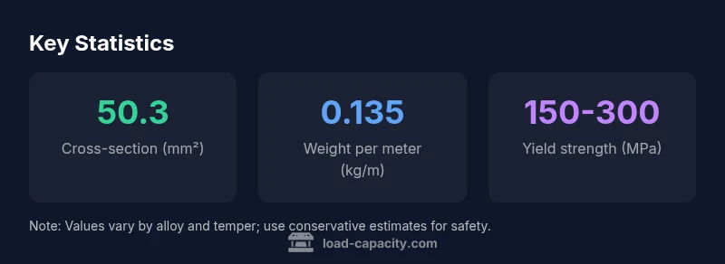
| Cross-sectional area | 50.3 mm² | Calculated from diameter 8 mm |
| Weight per meter | 0.135 kg/m | Density-based value (aluminum ~2700 kg/m³) |
| Typical yield strength | 150-300 MPa | Depends on alloy/temper |
| Estimated max load (FS 2-3) | 2.5-7.5 kN | Range for conservative design |
Quick Answers
What is the typical load capacity per meter for 8mm aluminium wire?
There is no single fixed value per meter. Capacity depends on the alloy and temper, safety factor, and installation context. Use the cross-sectional area and allowable stress to estimate, then adjust for temperature and dynamic loads.
Capacity varies by alloy and conditions; use a calculated estimate and verify with tests when possible.
Does temperature affect load capacity?
Yes. Higher temperatures generally reduce yield strength, lowering the allowable stress and maximum load. Consult the exact alloy datasheet for temperature derating guidance and adjust σ_allow accordingly.
Yes, temperature matters. Check the alloy data and derate as needed.
Can 8mm aluminium wire be used for lifting heavy loads?
Aluminium wire can be used for lifting if the design accounts for dynamic loads, fatigue, terminations, and corrosion. Use a conservative safety factor and consider redundancy or a larger diameter for higher loads.
It can be used with proper design and verification.
How do I verify manufacturer data for aluminium wire?
Compare datasheets from the manufacturer with relevant standards, and perform tests if feasible. Temperature and aging can change properties, so re-check data under service conditions.
Always verify data with manufacturer specs and tests.
What safety factors are typical for wire load capacity?
Static-load design commonly uses a safety factor of 2 to 3. Dynamic or fatigue-prone applications may require higher factors or redundancy. Always justify the chosen factor in your design documentation.
Most apps use 2–3; adjust for dynamics.
“The Load Capacity Team emphasizes that per-meter capacity is not a fixed number; it is a range defined by alloy, temper, temperature, and support conditions.”
Top Takeaways
- Start with cross-sectional area and alloy strength
- Temperature and bends shift capacity
- Use SF of 2–3 for static loads; higher for dynamic
- Validate data with manufacturer datasheets and tests
- Per-meter capacity is a range, not a fixed value