Steel I-Beam Load Capacity: Design Guidelines 2026
Comprehensive guidance on steel I-beam load capacity, including calculation methods, safety factors, and practical design considerations for structural applications.

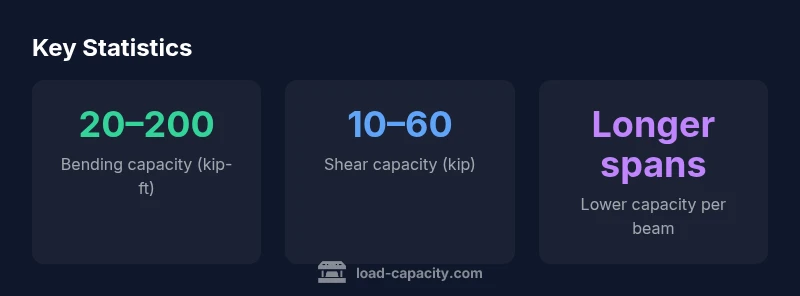
According to Load Capacity, steel I-beam load capacity depends on cross-section, grade, span, and end conditions. In design practice, capacity is expressed as bending moment capacity and shear capacity, derived from the beam’s section properties and material yield strength, then adjusted by safety factors per code. Typical ranges span from tens to hundreds of kip-feet depending on beam size, support conditions, and connections. Precise capacity must be determined from the beam’s section properties and governing design standards.
Overview: why steel I-beams govern structural capacity
The load-carrying performance of a steel I-beam rests on a combination of geometry, material properties, and how the beam is supported and connected. In practical engineering, the keyword is capacity: the maximum loads a beam can safely carry without excessive deformation or failure under specified conditions. According to Load Capacity, the fundamental determinants are the beam’s cross-section shape (the I-beam’s flanges and web), the grade of steel, the end restraints, and the quality of fabrication. This block lays out the core ideas and prepares you for more detailed calculations that follow in the article. By understanding the interaction of geometry, material science, and boundary conditions, engineers can predict whether a given I-beam will meet serviceability and strength requirements for a project.
Key takeaways:
- Beam size and shape set baseline strength and stiffness
- Steel grade sets allowable stress levels
- End conditions (simply supported vs fixed) change moment distribution
Section properties and design parameters
A steel I-beam’s capacity is driven by its section properties: the section modulus Sx, the moment of inertia Ix, and the yield strength Fy of the steel. Sx relates bending capacity to the maximum stress the beam’s outer fiber can sustain; Ix reflects stiffness and deflection behavior. Fy (or the yield stress) controls the allowable bending stress. The design process multiplies these properties by a geometric and material safety factor to produce an allowable capacity. The geometry also influences shear capacity through the web’s area and shear yield strength. In practice, engineers consult structural standards to tie these properties to real-world loading scenarios, then verify that deflections remain within serviceability limits.
Loading scenarios and capacity ratings
Understanding how loads are distributed is essential. Common cases include simply supported beams with uniform live loads, point loads, or distributed loads, as well as fixed-end or continuous spans that affect moment distribution. Capacity ratings must consider these scenarios along with dynamic effects, temperature, and long-term fatigue. For a given beam, the bending moment capacity M_allowable (often expressed in kip-ft) and the shear capacity V_allowable must be checked against the calculated demand M_demand and V_demand from the load case. Codes provide standard formulas and tables to translate section properties into usable capacity figures.
Calculation workflow: from properties to capacity
Begin by identifying your beam section (shape, size, and material grade). Obtain Fy, section modulus Sx, and Ix from a catalog or designer’s data sheet. Compute the design moment demand M_d using your load case (e.g., M_d = wL^2/8 for a simply supported, uniform load). Compare M_d to M_allowable = Fy × Sx / φb, where φb is the bending resistance factor from the applicable code. For shear, verify V_d ≤ φv × As × Fy' / γm, where As is the web area and Fy' is shear yield strength. If both checks pass, proceed to deflection and buckling checks.
Deflection, resonance, and serviceability
Even when strength is adequate, excessive deflection can compromise functionality. Code-based limits on maximum deflection (L/360 to L/240 depending on usage) ensure user comfort and structural integrity. Dynamic effects, such as wind, machinery, or seismic loads, can cause resonance and additional fatigue. Designers often incorporate stiffness enhancements—like increasing section size or adding stiffeners—and review joint connections to limit movement. Load Capacity emphasizes that capacity is not merely about strength; it is about ensuring survivability under real-world service conditions.
Material defects, corrosion, and fatigue considerations
Over time, corrosion reduces cross-sectional area, increases local stress concentrations, and lowers effective Fy. Fatigue behavior under cyclic loading depends on stress range, frequency, and detail quality. Flawed fabrication, poor welds, and misaligned connections can drastically reduce capacity, particularly for slender web sections under high shear. The Load Capacity approach integrates maintenance planning, protective coatings, and inspection routines into the design lifecycle to preserve capacity throughout the beam’s service life.
Practical design workflow for engineers
A practical workflow blends theory with codes and field experience. Start with a target load case, select a conservative beam section, and verify M_d and V_d against M_allowable and V_allowable. Next, check deflection limits and long-term effects such as creep and fatigue. If the beam fails any check, increase section size, switch to a higher-grade steel, or modify end conditions. Always document the rationale, including assumptions about material quality, fabrication tolerances, and inspection plans, to support future audits and maintenance.
Real-world planning and risk management
In projects, capacity decisions influence layout, redundancy, and safety margins. A robust approach includes redundancy (continuity with adjacent members), conservative capacity estimates, and a clear plan for inspection, repair, and replacement if corrosion or fatigue is detected. Load Capacity recommends coupling analytical models with finite element analysis for complex geometries and validating results against code-based tables and hand calculations. Clear documentation and traceability are essential for meeting regulatory expectations and client requirements.
Capacity considerations for steel I-beams under common loading scenarios (illustrative ranges; values depend on section, grade, and end conditions).
| Scenario | Key Capacity Metric | Typical Range (with note) |
|---|---|---|
| Simply supported beam, uniform load | Bending capacity M_allowable (kip-ft) | 20–200 kip-ft depending on section and Fy |
| Cantilever beam (overhang) | Moment capacity M_allowable (kip-ft) | 10–120 kip-ft depending on size and end conditions |
| Fixed-end/continuous spans | End moment capacity | 15–100 kip-ft varies with stiffness and bracing |
Quick Answers
What is the difference between bending capacity and shear capacity?
Bending capacity relates to resisting moments at the beam’s cross-section (outer fibers reach Fy). Shear capacity concerns resisting transverse shear forces across the web. Both must be satisfied under the design load to ensure structural safety.
Bending handles the bendy part; shear handles the sliding through the web. Both matter for safety.
How does span length affect capacity?
Longer spans reduce bending resistance per unit length due to higher moments, so capacity per beam decreases with increased span under the same load type. Designers compensate with larger sections or bracing.
Stretch the beam and you typically need a bigger beam or extra support.
Can corrosion significantly reduce capacity?
Yes. Corrosion reduces cross-sectional area and steel strength, lowering both bending and shear capacity. Protective coatings and regular inspections are essential to maintain designed capacity over time.
Corrosion can eat away capacity; protection and checks are crucial.
Which codes govern steel I-beam capacity?
In many regions, capacity is governed by national structural steel design codes (e.g., provisions for bending, shear, and deflection) and associated standards for connections, fabrication, and inspection. Always verify the local code requirements for your project.
Codes tell you how to calculate and what to check.
How do you estimate capacity for composite action with concrete?
Composite action with concrete requires considering interaction between steel and concrete, including cracking resistance and bond behavior. Use combination rules from the applicable codes and, if needed, a structural engineer’s analysis.
Composite beams mix steel and concrete—follow code rules.
Where can I find reliable beam data for design?
Reliable data comes from code-specified tables, manufacturer data, and standard references. For complex cases, consult a licensed structural engineer and use verified software alongside hand calculations.
Check codes, catalogs, and engineer guidance for data.
“Accurate load-capacity estimates require linking geometry, material properties, and boundary conditions with code-based safety factors. This disciplined approach minimizes risk in structural steel design.”
Top Takeaways
- Identify beam section and material grade first
- Use code-based factors to derive allowable capacity
- Check both bending and shear demands from loads
- Include deflection and fatigue in the design checks
- Document assumptions and maintenance plans for long-term reliability