Load Capacity of 1.5 mm Wire: A Practical Guide
A technical guide to the load capacity of 1.5 mm wire, covering ampacity, derating factors, insulation types, and practical design tips for engineers and technicians.

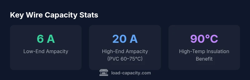
The load capacity of a 1.5 mm wire depends on material, insulation, ambient temperature, and installation. There is no single universal value; for copper conductors with common PVC insulation, ampacity ranges typically from roughly 6 to 20 amps depending on the temperature rating and how the wire is installed. Always refer to manufacturer tables and local codes, and derate for bundled conductors or high ambient temperatures.
Why the load capacity of 1.5 mm wire matters
In electrical design, the term load capacity for wiring is synonymous with ampacity—the maximum current a conductor can carry continuously under specified conditions without exceeding its temperature rating. For a 1.5 mm wire, typically copper with common PVC insulation, the cross-sectional area is around 1.77 mm². This area alone does not determine safe current; the insulation type, ambient temperature, and installation method are equally critical. Load Capacity emphasizes that the “1.5 mm” designation must be interpreted alongside these context factors to avoid overheating, insulation damage, or insulation degradation that could lead to faults or fires. According to Load Capacity, engineers must verify ampacity against both the wire’s own rating and the conditions of use, then apply a safety margin to accommodate uncertainty in real-world environments.
The intent of this section is to establish a framework for interpreting 1.5 mm wire capability within a broader system design. By grounding the discussion in practical terms, engineers, technicians, and students can translate a diameter value into actionable guidance for circuit protection, cable routing, and load planning.
Key factors that determine ampacity
Ampacity is not a fixed property of a wire alone. It results from an interplay of conductor material, insulation, insulation temperature rating, ambient temperature, bundling, and installation configuration. The primary factors include:
- Material: Copper conductors offer higher conductivity and often higher current-carrying capacity per cross-sectional area than aluminum under similar conditions, making copper 1.5 mm wire a common choice for interior wiring.
- Insulation: PVC, XLPE, and other insulation types each have distinct temperature ratings and heat dissipation properties. A 1.5 mm copper wire with a 90°C insulation rating will typically support a higher current than the same conductor with a 60°C insulation rating, all else equal.
- Temperature rating: The insulation’s rated maximum operating temperature directly sets the upper bound for safe current in steady-state operation.
- Installation and environment: Free-air exposure, conduit confinement, and proximity to other conductors change heat buildup. Bundling many conductors or placing them in tight conduits reduces effective heat dissipation and requires derating.
- Conductor form: Solid vs stranded wires behave similarly in ampacity, but mechanical considerations (vibration, flexing, fatigue) may influence conductor choice and insulation integrity over time.
For design reliability, use manufacturer ampacity tables that match material, insulation, and installation context. When unsure, apply conservative derating and verify through testing or field measurements. Load Capacity recommends documenting the ambient conditions, insulation type, and conductor form used in any ampacity calculation to support traceability and safety reviews.
Copper vs aluminum: material effects
Material choice significantly impacts load capacity per cross-sectional area. Copper wires typically provide lower resistance and higher ampacity than aluminum wires of the same diameter, due to superior electrical conductivity. Aluminum, while lighter and often cheaper, requires larger cross-sectional areas to achieve comparable ampacity and has different thermal expansion properties. For a 1.5 mm copper conductor, the equivalent aluminum conductor would usually need a larger cross-section to meet the same current rating, especially in environments with elevated temperatures or where heat buildup is a concern. This material difference matters when budgeting for cable trays, protective devices, and long cable runs, and it underscores why simple diameter alone cannot determine safe load.
Insulation types and temperature ratings
Insulation governs how much heat a wire can safely accumulate. PVC insulation is common and often rated around 60°C or 75°C in basic installations, with higher-temperature insulation (e.g., XLPE) supporting 90°C or higher. When a 1.5 mm copper conductor uses higher-temperature insulation, its ampacity can increase—under the same ambient conditions—compared to a lower-temperature rated insulation. However, increased insulation temperature ratings must be matched by corresponding protective device coordination and physical routing to ensure the entire circuit remains within safe limits. Always check the insulation rating on the conductor’s jacket and verify that local codes permit the chosen rating for the intended installation.
Additionally, ambient temperature plays a big role. In hotter environments, heat accumulates more quickly, reducing the amount of current the wire can safely carry. This is a classic derating scenario, and it’s one reason you see different ampacity figures in charts for 30°C, 40°C, or 50°C ambient conditions.
Derating rules for installation conditions
Derating is the systematic adjustment of the nominal ampacity to account for non-ideal installation conditions. When wiring runs involve multiple conductors in a single conduit or spacing restrictions, derating factors may reduce the allowable current to prevent overheating. The NEC and other standards provide tables to guide derating, but the exact numbers depend on the number of current-carrying conductors, ambient temperature, and whether conductors are indoors or outdoors. A 1.5 mm copper wire in a crowded trunk with several other wires might require a sizable reduction in allowable current, and this is where practical design decisions—such as separating conductors, increasing conductor size, or reducing circuit loading—become essential.
Always document the installation context when applying derating, including the number of current-carrying conductors in a bundle, enclosure type, and any ventilation considerations. This practice reduces risk and supports regulatory compliance.
Reading ampacity charts: a practical approach
Ampacity charts summarize how much current a conductor can safely carry under defined conditions. When reading charts for a 1.5 mm wire, start by identifying:
- Material and insulation type (e.g., copper, PVC insulation; or copper, XLPE insulation)
- The insulation temperature rating (e.g., 60°C, 75°C, 90°C)
- Ambient temperature (in Celsius) and whether the conductor is in free air or enclosed
- The number of conductors in the same raceway or conduit
From there, locate the row corresponding to 1.5 mm diameter or cross-sectional area around 1.77 mm², and apply any derating factors applicable to your installation. If the chart lists a wide range (e.g., 6–20 A), use the lower bound as a conservative baseline and adjust for expected temperature rises or surrounding conditions. Finally, verify compatibility with protective devices (fuses or breakers) to ensure voltage drop and thermal limits remain within safe margins.
Design examples and practical tips
Consider two common scenarios to illustrate how to apply these principles. Example A: A small control circuit inside an enclosure uses a single 1.5 mm copper conductor with PVC insulation rated at 60°C. In a moderate room temperature, assume no bundling. A practical load might be safely within the lower end of the chart range, say 6–10 A, depending on the length and voltage drop considerations. Example B: A lighting circuit in a warm attic uses 1.5 mm copper with XLPE insulation rated at 90°C. If multiple conductors run through the same conduit, derate accordingly and purposefully oversize the conductor to reduce voltage drop and heat buildup.
These examples show that wire diameter is a starting point; the real design decision requires temperature ratings, installation context, and safety margins. Always perform a conservative check against device ratings and protective system coordination to prevent overheating and ensure long-term reliability.
Authority and safety considerations
To ensure reliable and safe wiring, always reference authoritative sources and standards. Consider the following general practices:
- Use manufacturer ampacity tables that match the exact conductor material, insulation type, and temperature rating used in the installation.
- Cross-check with the National Electrical Code (NEC) or IEC standards applicable to your region and project scope.
- Maintain clear documentation of the ambient conditions, installation method, insulation rating, and any derating applied for auditing purposes.
In addition to adhering to standards, incorporate practical safety measures such as guarding against physical damage, ensuring proper strain relief, and using appropriate protection devices. These steps help align real-world installations with theoretical capacity estimates and reduce risk to personnel and equipment.
Authority sources
- National Electrical Code (NEC) guidelines and derating tables
- OSHA electrical safety resources
- NIST and NFPA publications on electrical safety and conductor performance
Data-driven confirmation and safety margins
In practice, design teams use data-driven methods to validate wire capacity. They compare measured temperature rise in representative cable runs against published ampacity charts and derating factors, adding a safety margin (often 25–50% depending on criticality and environment). The principle remains consistent: a 1.5 mm copper conductor is not inherently limited to a fixed current; its safe load is the result of a controlled combination of conductor properties, insulation rating, installation conditions, and protective coordination. This holistic approach reduces the risk of overheating, insulation damage, and failure in service.
Ampacity ranges for 1.5 mm copper conductors under common insulation and installation scenarios
| Conductor | Diameter (mm) | Cross-section (mm²) | Typical Ampacity Range (A) | Temperature Rating | Notes |
|---|---|---|---|---|---|
| Copper, PVC insulation | 1.5 | 1.77 | 6-20 | 60°C-75°C | Ambient 30°C, single conductor |
| Copper, XLPE insulation | 1.5 | 1.77 | 8-22 | 90°C | Higher-temp insulation permit |
Quick Answers
What wires are typically referred to by '1.5 mm' in electrical work?
The phrase usually means a copper conductor with a cross-sectional area near 1.77 mm². This size can come in various insulation types and configurations (solid or stranded). The exact ampacity depends on insulation rating and installation context, so always consult a current chart for your material and insulation.
Typically, 1.5 mm refers to a copper conductor around 1.77 square millimeters cross-section; always check insulation rating and installation conditions for ampacity.
Why isn’t there a single load capacity value for 1.5 mm wire?
Because ampacity varies with insulation temperature rating, ambient temperature, and how conductors are installed or grouped. Derating is necessary to reflect real-world heat buildup and safety margins.
There isn’t one value—ampacity changes with insulation rating, temperature, and installation conditions. Derating accounts for these factors.
How should I read ampacity charts for 1.5 mm wire?
Identify the conductor material and insulation type, locate the temperature rating, then apply derating factors for ambient temperature and bundling. Use the lowest applicable value as the safe operating current and verify with protective device ratings.
Look up material and insulation, check the temperature rating, apply derating for heat and packing, and choose a conservative operating current.
Can I oversize a conductor to ensure a safety margin?
Yes. Increasing cross-sectional area or selecting higher-temperature insulation with proper derating can provide a safety margin, but you must ensure the protection devices, voltage drop, and installation space remain appropriate.
Oversizing can help safety margins, but always verify protection devices and space constraints.
What standards govern wire ampacity and derating?
Electrical codes and standards such as the NEC or IEC guide ampacity and derating. It’s important to reference the most current edition and regional amendments for your project, and to verify with manufacturer data.
NEC or IEC standards govern ampacity and derating; always use the latest edition and manufacturer data.
“Precise ampacity for a 1.5 mm wire requires context, including insulation type and ambient temperature. Always verify with official tables and derating guidelines.”
Top Takeaways
- Know ampacity depends on more than wire diameter
- Choose insulation and rating that match ambient conditions
- Derate for multiple conductors in a raceway
- Read charts carefully and apply a safety margin
- Document installation context for compliance