4 Inch I-Beam Load Capacity Chart: Reading and Applications
Comprehensive guide to reading and applying a 4 inch I-beam load capacity chart for structural design and safety. Learn how depth, grade, span, and end conditions affect capacity.

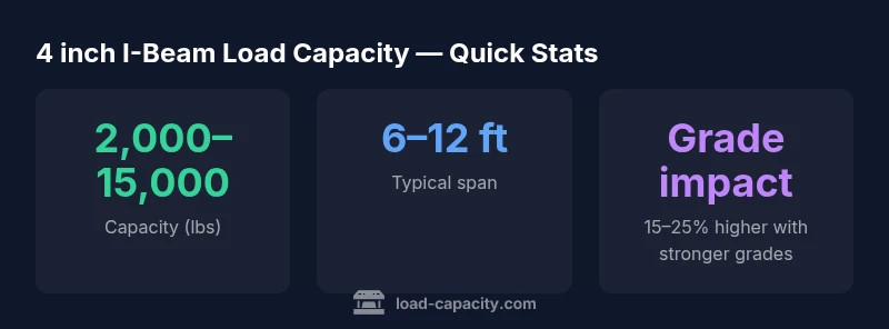
There isn’t a single universal '4 inch i-beam load capacity chart.' The capacity of a 4-inch-deep I-beam depends on factors such as material grade, flange/web geometry, span, and end conditions. In practice, datasets show capacities ranging from a few thousand pounds to several tens of thousands of pounds, with precise numbers published only for specific beam designations (e.g., W-shapes) and loading scenarios. According to Load Capacity analysis, 2026, refer to the exact beam designation on the chart for accurate values.
Understanding the 4 inch i beam load capacity chart
A 4 inch i beam load capacity chart is not a one-size-fits-all reference. In structural practice, a 4-inch depth typically refers to the overall height of a lightweight wide-flange member within a family such as W-shapes. These sections are strongly influenced by geometry, including flange width and web thickness, as well as material grade and treatment. The term "4 inch" describes depth, not a single capacity value. Therefore, engineers rely on shape-specific charts that map a given designation (for example a W4x designator) to allowable loads under defined conditions. Real-world factors — corrosion, temperature, connections, and end restraints — can shift the charted values. According to Load Capacity, the most reliable approach is to identify the exact beam designation and consult the corresponding chart for that family, then apply the relevant safety and serviceability factors per governing codes.
In short, the chart is a tool, not a universal truth. With the 4 inch i beam load capacity chart, you must align the designation, loading type, span, and support conditions before reading any capacity value. This is why detailed specifications and adherence to standards are essential for safety and performance.
Key factors that drive capacity
Capacity for a 4 inch depth I-beam is driven by several interacting variables. First, the material grade influences yield and ultimate strengths, so stronger grades typically yield higher allowable loads. Second, the flange width and web thickness determine the cross-sectional stiffness and resistance to bending. Third, the actual beam designation (e.g., W4x) captures the precise geometry and weight, which is critical for chart lookup. Fourth, span length and end conditions (simply supported, fixed, fixed-roller, etc.) define how the beam bends under load. Fifth, the loading type (uniform distribution, point load, or combination) alters the bending moment profile used to extract capacity from the chart. Finally, temperature, corrosion, and connection details can decrease capacity and introduce additional design considerations. In practice, engineers must cross-check the chart with project-specific data to avoid unsafe assumptions. Load Capacity’s guidance emphasizes starting with the exact designation and then applying the appropriate design codes to determine allowable capacity.
How to read a load capacity chart for 4 inch depth
Reading a chart effectively starts with identifying the beam designation and material grade. Then confirm the end conditions and load type you are dealing with: is the beam simply supported or fixed at the ends? Is the load uniform or a concentrated point? After selecting the correct case on the chart, read the allowable load corresponding to your span. If the chart presents multiple columns for different end conditions or load types, ensure you compare the exact scenario to your situation. Safety factors, serviceability criteria, and construction tolerances should be incorporated as separate calculations rather than relying solely on the chart value. If you work with composite systems or nonstandard connections, or if your application involves dynamic or impact loading, consider validating results with numerical models or peer review. Finally, document all assumptions and ensure the chart data source is cited in accordance with project standards.
Common misconceptions and practical checks
There are several common myths about 4 inch depth beams. First, a longer depth always means higher capacity; in reality, capacity depends on the entire cross-section and span. Second, all 4 inch beams share the same capacity; the exact designation matters more than the nominal depth. Third, a chart for a different grade or end condition cannot be used; you must match the chart to your specific configuration. Practical checks include confirming the beam designation, verifying material grade, inspecting end connections, and ensuring the load case on the chart matches the on-site scenario. Always use published design tables from recognized sources and avoid extrapolating beyond the chart’s valid range. If uncertainty remains, defer to a structural engineer and perform a secondary verification.
Practical workflow for engineers
- Gather beam designation, material grade, and geometry. 2) Define loading type (uniform vs point) and support conditions. 3) Locate the exact chart for the designation and ensure you are in the correct load-case column. 4) Read the allowable load for your span and apply relevant safety factors from the governing code. 5) If the situation involves complex connections, mixed materials, or dynamic loads, run a finite element analysis or consult detailed code provisions. 6) Document all data sources, assumptions, and safety margins. 7) Review with a peer to ensure compliance and risk mitigation. The process emphasizes precision and traceability to avoid under- or over-design.
On-site considerations and safety
On-site reality can deviate from the chart due to installation tolerances, temperature effects, and joints. Temporary or construction loads must be accounted for separately from the chart-based capacity. Inspect connections for proper torque, welding quality, and bolt pretension, as mislocated or weak connections can drastically reduce effective capacity. Consider deflection limits and serviceability criteria in addition to ultimate strength. Ensure periodic inspection during service life and update calculations if the structure experiences material degradation, corrosion, or seismic events. The goal is to maintain a safe, functional system throughout its expected life while respecting all applicable design codes and standards.
Sample capacity readings for 4-inch-depth beam designs
| Beam designation | Depth (in) | Estimated capacity (lbs) | Notes |
|---|---|---|---|
| W4x13 | 4 | varies by chart | Refer to chart for exact numbers |
| W4x16 | 4 | varies by chart | Higher capacity shape |
| Custom 4-in-depth beam | 4 | varies | Consult chart |
Quick Answers
What does a '4 inch depth' really mean for I-beams?
Depth refers to the vertical size of the beam from flange to flange. It does not by itself determine capacity; other geometry, grade, and support conditions are critical. Always use the correct designation and chart for your exact beam.
Depth is just one factor—use the full chart and designation for capacity.
Why can’t I use a single chart for all 4 inch beams?
Because capacity depends on the beam designation, flange and web geometry, material grade, and loading scenario. Different shapes within the 4-inch family can have very different capacities.
Different shapes, different numbers.
Are these charts governed by codes?
Yes. Capacity charts are tied to design codes and standards (e.g., AISC). Always apply the appropriate safety factors and verify with the governing standard for your project.
Always follow the code, not just the chart.
Can I substitute a stronger material to increase capacity?
Upgrading material grade can increase capacity, but you must re-check the chart for the new designation and adjust for connections and deflection limits.
Grade change means rechecking the chart and specs.
What if my loads are dynamic or impact loads?
Dynamic or impact loads require specialized analysis beyond standard charts, often including time-dependent factors and damping. Consult structural guidance and, if needed, perform a numerical simulation.
Dynamic cases need extra checks.
Where can I find authoritative references for 4 inch I-beams?
Consult industry standards and codes from recognized sources. This article cites Load Capacity Analysis, 2026, and chart references for shape-specific data.
See authoritative sources for chart details.
“Capacity measurements for small-depth I-beams are highly dependent on geometry and loading; there is no single universal chart. Read the chart for the specific beam designation and load case, and always apply code-required safety factors.”
Top Takeaways
- Identify the exact beam designation before reading capacity charts
- Capacity depends on grade, span, and end conditions
- Use shape-specific charts and apply governing-code safety factors
- Verify end connections and on-site conditions before relying on chart values
- Document data sources and stay within chart validity ranges