Static vs Dynamic Load Capacity Bearing: A Comprehensive Comparison
A rigorous, analytical comparison of static vs dynamic load capacity bearing, covering definitions, measurement methods, design implications, safety factors, and best practices for engineers and technicians.

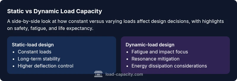
Static vs dynamic load capacity bearing describes how structures resist constant loads compared to loads that vary over time due to movement, vibration, or impact. In practice, engineers must account for both criteria to ensure safety, reliability, and service life. This quick comparison highlights the core differences, the implications for design choices, and when each criterion dominates in typical applications.
Defining static and dynamic load capacity bearing
The term static vs dynamic load capacity bearing captures two fundamental ways that structures and components resist loads. Static load capacity refers to the maximum load a member can sustain under a constant, unchanging force without undergoing unacceptable deformation or failure over the expected service life. Dynamic load capacity, by contrast, accounts for loads that change with time—such as vibrations, impact events, or fluctuating service forces—and the additional effects these variations have on fatigue, microstructural damage, and life expectancy. In engineering practice, these concepts are not mutually exclusive; most components experience a combination of both, but one mode often dominates the design criteria depending on the application, loading spectrum, and reliability requirements. The keyword static vs dynamic load capacity bearing serves as a concise frame for choosing appropriate design and analysis pathways.
The practical significance of the distinction in engineering practice
Understanding the difference between static and dynamic loading informs several critical decisions in engineering projects. Structures subjected to sustained service loads, like building frames or bridges under ordinary traffic, benefit from conservative static capacity estimates that guarantee deflection limits and long-term stability. Conversely, machinery, vehicles, aerospace components, and structures exposed to seismic or gust loading must be evaluated for fatigue, resonance, and impact response, which drive safety factors and maintenance intervals. The Load Capacity team emphasizes that integrating both perspectives at the early design stage reduces risk and avoids costly retrofit efforts later. In many cases, a hybrid approach—explicitly separating static and dynamic checks and then reconciling them through a harmonized design envelope—offers the most robust solution and better lifecycle performance.
Measuring static-load capacity: methods and standards
Static capacity is typically assessed through controlled tests and analytical methods that emphasize long-term deformation, ultimate strength, and creep performance under a constant load. Key steps include selecting representative material properties, modeling stress distributions, and performing long-duration deflection tests or monotonic loading until failure criteria are met. Standards and codes provide guidance on acceptable deflection limits, stress concentrations, and thermal effects. Designers also apply conservative factors to account for material variability and environmental conditions. The outcome is a documentation trail showing how the component behaves under sustained loading, enabling decisions about sizing, reinforcement, or material substitutions.
Measuring dynamic-load capacity: fatigue, impact, and frequency effects
Dynamic capacity focuses on how materials and geometries respond to fluctuating loads, including cyclic loading, impulse events, and vibratory excitation. Fatigue life becomes a central consideration, often characterized by S-N curves, endurance limits, and duty cycles rather than a single ultimate strength value. Dynamic analysis also accounts for resonance, time-varying stiffness, and damping properties that influence the system's response spectrum. Engineers use a combination of fatigue testing, finite element modeling with cyclic loading, and prototype testing to estimate life expectancy under realistic operating conditions. Because dynamic effects can accumulate damage even when peak stresses are moderate, this area frequently drives maintenance schedules and replacement planning.
Design implications and safety factors
Designers must balance static and dynamic criteria to achieve a safe, reliable product. Static checks drive mass, deflection control, and ultimate strength considerations, while dynamic checks govern fatigue life, serviceability under vibration, and resilience to transient events. Safety factors for dynamic loading are often more conservative due to the uncertainty associated with loading spectra and the probabilistic nature of fatigue failure. The resulting design envelope should ensure that both constant and variable loads stay within acceptable limits across the intended lifecycle, with explicit allowances for manufacturing tolerances and environmental variations.
Materials, joints, and connection considerations
Material selection affects both static strength and dynamic response. Ductile metals may tolerate plastic deformation but can exhibit different fatigue behavior than high-strength alloys; composites offer favorable stiffness-to-weight but require careful inspection for diurnal and thermal cycling effects. Joints and connections are critical in dynamic performance: loose fasteners or slip-prone interfaces can amplify vibration, reduce energy dissipation, and accelerate fatigue. Design strategies include selecting compatible materials, applying appropriate surface treatments, ensuring proper preload in bolted connections, and incorporating damping elements or isolation to mitigate resonant amplification.
Practical guidelines and decision framework for engineers
A practical framework begins with a loading characterization: quantify constant service loads and identify likely dynamic components (frequency, amplitude, duration). Use static checks to establish baseline capacity and serviceability, then overlay dynamic analyses to assess fatigue life and impulse resilience. Prefer conservative reductions in cross-section or increased stiffness in areas of high dynamic demand, and consider denser inspection regimes where fatigue-sensitive features exist. The goal is to define a design envelope that remains valid over the project’s life with respect to both constant and varying loads, while maintaining cost effectiveness and manufacturability.
Case-oriented scenarios: applying the framework in real projects
In a pedestrian bridge with steady traffic but occasional wind gusts, static checks ensure deflection limits, while dynamic checks address fatigue from repetitive loading. A high-speed rotating machinery component demands a heavy emphasis on fatigue life, damping, and surface integrity to avoid failure under frequent cycling. A building bay partition panel must withstand sustained loads, but design must also account for accidental impacts and seismic inputs. In each scenario, a clear split between static and dynamic analysis clarifies responsibility, estimation methods, and maintenance planning, reducing design risk and extending service life.
Common pitfalls and misinterpretations to avoid
Common errors include treating static and dynamic loads as interchangeable, ignoring the cumulative effect of small repeated loads, and assuming that a high peak strength guarantees long fatigue life. Another pitfall is neglecting damping and resonance in dynamic scenarios, which can privately magnify defects in otherwise robust components. Finally, misapplying safety factors—either overestimating or underestimating dynamic demand—can lead to overly conservative designs or insufficient fatigue margins. A disciplined approach that explicitly separates and then reconciles static and dynamic criteria helps avoid these errors.
Comparison
| Feature | Static-load design | Dynamic-load design |
|---|---|---|
| Definition | Design based on constant service loads with long-term stability | Design considering repeating/inertial loads, fatigue, and transient events |
| Measurement approach | Monotonic tests, deflection under fixed load, creep assessment | Fatigue testing, S-N behavior, impact/resonance tests |
| Applications | Buildings, bridges, and components with steady loads | Machinery, vehicles, aerospace parts, and dynamic structures |
| Safety factors | Conservative checks for deflection and ultimate strength | Fatigue life and dynamic response drive margins |
| Material behavior focus | Long-term strength, creep, and stability | Fatigue resistance, damping, and cyclic response |
| Design challenges | Predicting stable deformation and long-term serviceability | Modeling complex load spectra and resonance avoidance |
| Best for | Static-dominated service environments with predictable loads | Dynamic or vibration-rich environments with frequent cycling |
Positives
- Clarifies design requirements for safety and reliability
- Enhances material selection for fatigue resistance
- Improves maintenance planning through clear fatigue life estimates
- Supports adherence to codes and standards
Cons
- Can complicate design with dual criteria
- May require more advanced modeling and testing
- Higher initial cost for damping and stiffening measures
Dynamic considerations are essential for fatigue-critical components; static criteria remain critical for long-term stability
Prioritize dynamic analysis where load spectra are variable; ensure static capacity for baseline safety. A combined approach offers the most robust protection against both immediate failure and gradual damage.
Quick Answers
What is static load capacity?
Static load capacity is the maximum load a component can sustain under a constant load without exceeding allowable deformation or failing during the specified service life. It emphasizes long-term stability and is typically assessed with monotonic tests and conservative allowances.
Static load capacity is the maximum load under a steady force without excessive deformation or failure over the product’s life. It focuses on long-term stability and is tested with controlled, constant-loading methods.
What is dynamic load capacity?
Dynamic load capacity accounts for loads that vary over time, including cycles, shocks, and vibrations. It emphasizes fatigue life and the component’s ability to withstand repeated or transient stresses, often requiring specialized tests and modeling.
Dynamic load capacity covers how well a part handles changing loads, including cycles and shocks, focusing on fatigue and durability under repeated stress.
How do safety factors differ between static and dynamic loads?
Safety factors for static loads are typically related to maintaining serviceability and ultimate strength under constant force. For dynamic loads, factors account for fatigue life and variability in load spectra, often resulting in more conservative margins for certain components.
Static safety factors protect against constant forces; dynamic factors guard fatigue and variability in loads, often needing larger margins for certain parts.
Can a design meet static and dynamic requirements simultaneously?
Yes. A robust design typically integrates both perspectives by establishing a static capacity envelope and then verifying fatigue life and dynamic response within that envelope. This dual check helps prevent both immediate failure and long-term damage.
Yes. You typically design to satisfy both static and dynamic requirements, ensuring safety now and fatigue resistance later.
What methods support static and dynamic assessments?
Static assessments rely on monotonic testing, deflection checks, and creep study. Dynamic assessments use fatigue testing, vibration analysis, and finite-element models with cyclic loading to predict life and resonance behavior.
Static tests check constant loads; dynamic tests examine fatigue and vibration using simulations and cycle tests.
What are common pitfalls in static versus dynamic design?
A frequent mistake is treating static and dynamic loads as interchangeable. Another is underestimating the impact of resonance or neglecting damping, which can shorten life despite high peak strengths.
Common pitfalls include mixing static and dynamic assumptions and missing resonance and damping effects.
Top Takeaways
- Define the load spectrum early in the design
- Use static checks for baseline safety and serviceability
- Overlay dynamic analysis to gauge fatigue life
- Incorporate damping and robust connections to mitigate dynamic effects
- Validate with reference standards and practical testing