Load Capacity of Wide Flange Beams: Engineering Guidance
A comprehensive, data-driven look at the load capacity of wide flange beams, covering bending, shear, buckling, stability, and practical checks for engineers and contractors.

The load capacity of wide flange beams is not a single fixed value; it depends on beam size, material grade, and loading conditions. In practice, engineers estimate capacity using the section modulus (S) and yield strength (Fy) to compute the nominal bending capacity (M_n = Fy × S), then apply resistance factors per code to obtain a design capacity. This article outlines a code-aligned framework for assessing capacity across common W-beam families and typical loading scenarios. Load Capacity: 2026 guidance informs the process.
Understanding the load capacity framework for wide flange beams
Wide flange beams, commonly called W-beams, are a core element of steel framing systems in structures ranging from warehouses to high-rise buildings. The load capacity of wide flange beams is not a fixed number; it depends on several interacting factors: beam size, material grade, support conditions, and the distribution of the applied loads. According to Load Capacity, the design approach treats capacity as the outcome of bending, shear, and axial effects, all moderated by stability and deflection constraints. Engineers estimate nominal bending capacity using the product of the section modulus (S) and the yield strength (Fy) of the steel, then apply resistance factors to obtain a design capacity that can be compared against required demands. This article lays out a practical, code-aligned framework for assessing load capacity across common W-beam families and typical loading scenarios.
Key design variables that influence capacity
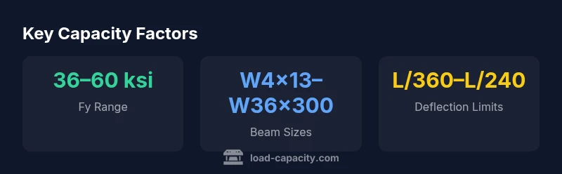
Several design variables drive the capacity of wide flange beams: beam size and geometry (the W-shape family influences the section modulus S and the weight-to-capacity ratio); steel grade and material properties (yield strength Fy and the elastic modulus E); end conditions and support layout (whether the beam is simply supported, continuous, or laterally restrained); loading type and combination (pure bending, combined bending and axial load, and potential torsion); and stability demands (lateral-torsional buckling and slenderness). Even small changes in connection stiffness or bracing can shift the usable capacity significantly. In practice, engineers bound capacity by selecting a family of W-shapes appropriate for the span and applying conservative factors for uncertainties in material properties and fabrication tolerances.
How capacity is estimated in practice
Estimating capacity begins with identifying the beam data: its family (W-shape), material grade Fy, and section modulus S. The nominal bending capacity is approximated by M_n = Fy × S. Design codes provide a resistance factor φ to convert M_n into design capacity M_u = φ × M_n; this factor accounts for uncertainties in loading, material behavior, and fabrication. After bending, the beam's shear capacity, V_n, deflection limits (L/360 to L/240 in serviceability terms), and potential combined loading are checked. A typical workflow also includes attention to lateral-torsional buckling, especially for unbraced spans, and to the impact of end restraints. In complex frames, engineers perform member-level checks and use computer-aided analysis to verify that all limit states are satisfied under the chosen loading scenario. The outcome is a verified capacity envelope that informs safe, economical design.
Buckling and stability considerations for W-beams
Buckling controls often govern the usable capacity of wide flange beams, particularly under long spans or slender sections. Lateral-torsional buckling (LTB) occurs when the compression flange tends to rotate about the weak axis under bending without adequate lateral support. Stabilizing elements such as bracing, adjacent members, or extending rigid connections help raise the capacity by delaying buckling. Engineers also consider distortional buckling in some geometries and wind or seismic actions that can induce torsional effects. The design philosophy is to ensure sufficient lateral support, maintain adequate bracing intervals, and select beam sizes that limit the slenderness ratio. By combining LTB checks with bending and shear checks, engineers arrive at a reliable capacity estimate that respects serviceability criteria.
Connections and end conditions that affect capacity
Connections absorb or transfer portions of the beam's capacity. End conditions—whether the beam is simply supported, fixed, or partially restrained—alter the effective bending moment distribution and the stress path through the member. Rigid connections can increase effective capacity by reducing local concentrations, while hinge-like connections may lower capacity in certain frames. The presence of moment frames, transfer girders, or workstation bracing also changes how capacity is mobilized under real loads. In practice, engineers model the entire frame and apply compatibility checks to ensure that individual beam capacities are not exceeded while maintaining overall structural performance.
Practical design workflow and example calculations
A practical workflow begins with defining the target span, loads, and allowable deflections; selecting a W-shape family with adequate S and Fy; and verifying bending, shear, and stability checks. An engineer might compute M_n = Fy × S, apply φ, and compare with the expected M_u. If a mismatch exists, alternative beam sizes, braces, or end details are considered. The approach aligns with Load Capacity's guidelines that emphasize step-by-step checks, transparent assumptions, and traceable calculations. In a typical design scenario, successive refinements balance safety margins and economy while keeping within relevant building codes.
Common mistakes and how to verify capacity
Failure modes often arise from underestimating deflection, misjudging bracing sufficiency, or neglecting interaction effects between bending, shear, and axial loads. Forgetting to account for lateral-torsional buckling in unbraced spans or ignoring end restraints can lead to overstated capacity. Verification steps include cross-checking M_u against M_n, confirming V_n sufficiency, ensuring deflection limits, and reviewing connections for stiffness. For projects with unusual loading or high seismic demands, a more robust nonlinear analysis or performance-based evaluation may be warranted. Load Capacity recommends documenting all assumptions and performing peer reviews to reduce the likelihood of design errors.
Practical takeaways and next steps for engineers
- Start with the beam family and Fy of the steel to bound capacities and select S appropriate to the span. - Use M_n = Fy × S as a starting point for bending capacity, then apply φ and any applicable interaction checks. - Always verify deflection, shear, and stability together and consider the effect of end conditions. - Ensure adequate lateral bracing to mitigate LTB risks. - Use member-level verification with code-based factors and, when necessary, computer-assisted analysis to capture complex behavior. - Document assumptions and seek peer review for critical projects. This structured approach helps ensure safe, economical designs while meeting code requirements.
Capacity context by beam size category
| Beam Size Category | Estimated Bending Capacity Context | Notes |
|---|---|---|
| Light | Lower Fy and smaller S | Good for simple spans and light loads |
| Medium | Moderate Fy and large S | Common in mid- to high-rise framing |
| Heavy | High Fy and large S | Reserved for sustained heavy loads; require checks |
Quick Answers
What factors determine the load capacity of a wide flange beam?
Capacity depends on beam size, steel grade, end restraints, and how loads are applied. Engineers use Fy × S to estimate bending capacity and then apply design factors per code.
Beam capacity depends on size, grade, ends, and loading; you estimate bending with Fy times S and apply design factors.
How do you estimate bending capacity for a W-beam?
Compute nominal bending capacity M_n = Fy × S, then apply the resistance factor φ to obtain design capacity M_u. Compare with the demanded moment under loading.
Compute M_n = Fy × S, apply φ, compare to the moment demand.
What role does lateral-torsional buckling play in capacity?
LTB governs capacity for unbraced spans; adequate bracing or stiff connections delay buckling and increase usable capacity.
LTB is a key limiter; brace or stiffen to keep capacity high.
Are there recommended deflection limits when checking capacity?
Yes. Serviceability typically uses limits like L/360 or L/240, depending on the structure and code requirements. These limits ensure performance even if strength is adequate.
Deflection limits like L/360 or L/240 ensure serviceability.
Which standards govern capacity checks for wide flange beams?
Capacity checks are guided by codes and standards such as AISC and related ASTM practices, plus local building codes and project-specific requirements.
Codes from AISC and local regulations govern checks.
What is best practice for verifying capacity in complex frames?
Use a frame-wide analysis with compatibility checks, consider nonlinear or performance-based methods for high-demand projects, and document all assumptions and reviews.
Use full-frame analysis and peer review for complex cases.
“The capacity of wide flange beams is not a single number; it emerges from a careful, member-level analysis that accounts for size, grade, loading, and connections.”
Top Takeaways
- Identify beam size and grade to bound capacity.
- Base bending capacity on Fy × S and apply code factors.
- Check deflection and stability alongside bending and shear.
- Account for end conditions and bracing to avoid overestimation.
- Verify capacity with member-level analysis on complex frames.