Beam Load Capacity Calculator: Safe Beam Sizing Guide
Learn how to size rectangular beams safely using a beam load capacity calculator. This guide explains inputs, interpretation, and best practices for engineers and builders.

What a beam load capacity calculator does
According to Load Capacity, a beam load capacity calculator is a design aid that estimates the maximum uniform load a simply supported beam can carry without exceeding its bending strength. The calculator uses four core inputs: span length (L), cross-section width (b) and depth (h), and the material's allowable bending stress (sigma_allow). With those values, it computes a safe load per meter (often expressed as kN/m) and an overall safety range. The approach is geometric and material-based, not a substitute for professional judgment; it helps engineers and technicians sanity-check preliminary sizing before detailed analysis or on-site testing. The math leverages the classic M = wL^2/8 relationship for uniform loads on simply supported beams, and S = b*h^2/6 for a rectangular section. Small changes in span or section height can push the required load capacity up or down dramatically, so sensitivity checks are essential.
Key factors that influence beam capacity
Beam capacity hinges on geometry, material strength, and support conditions. Span length dramatically changes bending moments; longer spans raise the required bending capacity. The cross-section geometry, specifically width (b) and depth (h), determines the section modulus S = b*h^2/6; a deeper beam increases S and thus supports higher loads. Material strength, typically expressed as allowable bending stress, sets the stress limit before yielding or failure. Real-world designs must also consider lateral-torsional buckling, shear capacity, and local bending at supports, which the basic w_max formula ignores. Support conditions matter too: a simply supported beam versus a fixed-ended beam redraws the moment distribution and reduces maximum allowable loads. Temperature effects, moisture, and long-term creep can lower effective strength. Finally, safety factors and design codes require adjustments to the raw bending capacity to account for uncertain loads, dynamic effects, and construction tolerances.
How to interpret calculator results
The calculator returns a maximum uniform load per meter (w_max) that the beam can carry under the specified inputs. Read w_max as the per-meter capacity; to estimate the total load across the span, multiply w_max by the span length L. If your design uses a safety factor, apply it after reading the raw value (divide by the factor). The units are typically kilonewtons per meter (kN/m) for distributed loads, with related outputs in kilonewtons (kN) when calculating total span reactions. Context matters: the simple formula assumes a rectangular section and a simply supported condition. For different cross-sections or support types, the available capacity changes; use the calculator as an initial sizing check, not the final design authority. Load Capacity analysis shows that modest changes in L or h can dramatically change w_max, underscoring the importance of input accuracy and code-compliant design.
Worked example: steel beam in a 6 m span
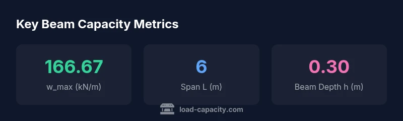
Consider a rectangular steel beam with L = 6 m, width b = 0.20 m, depth h = 0.30 m, and an allowable bending stress sigma_allow = 250 MPa. Compute S = bh^2/6 = 0.2(0.3^2)/6 = 0.003 m^3. Then w_max = 8sigmaS/L^2 = 8250e60.003/36 ≈ 166,667 N/m ≈ 166.67 kN/m. The total load across the span would be w_max * L ≈ 1,000 kN. This example illustrates how a modest change in depth or span yields large changes in capacity, underscoring the value of early sizing checks before selecting a final beam size. Remember to apply a safety factor before construction.
Safety factors, codes, and limitations
Real-world designs require safety factors to account for uncertainties in loads, material properties, and construction quality. Typical factors range from 1.5 to 2.0 for structural beams in non-critical applications, depending on jurisdiction and code. The calculator's straight-line result should be reduced by the chosen factor before final sizing. Do not rely on a single calculation for critical structures; incorporate deflection limits, dynamic loads, fatigue, and erosion effects if applicable. Always cross-check results against relevant building codes (e.g., structural safety standards) and obtain review from a licensed professional engineer.
Cantilever beams and other configurations
The basic w_max formula targets simply supported beams with uniform loads. For cantilever beams, the maximum moment is M = wL^2/2, and the corresponding allowable w becomes w = 2sigmaS / L^2. This effectively halves or reduces capacity compared to a simply supported span, depending on fixed-end effects. Continuous beams or frames distribute moments differently, requiring more advanced analysis (e.g., slope-deflection or finite element methods). In practice, use the calculator for initial sizing, then switch to engineering analysis for cantilever or continuous configurations. If your project involves layered materials, composite sections, or nonuniform loads, consult a structural engineer to adjust the model accordingly.
Materials and cross-section shapes beyond rectangles
The calculator uses a rectangular cross-section in its core calculation because S = b*h^2/6 is straightforward and intuitive. Real beams come in I-beams, hollow sections, or composite shapes where the section modulus is different. For other shapes, convert the cross-section into an equivalent rectangular bottle that yields the same S, or use a dedicated formula for that geometry. Steel, wood, or reinforced concrete each have distinct allowable bending stresses and failure modes. Always ensure that allowable stress values match the material and loading scenario, and apply compatibility checks with connection details, bolt patterns, and support conditions.
Practical sizing workflow for projects
A clear sizing workflow helps teams avoid over- or under-sized beams. Start by defining the span L and selecting a plausible cross-section based on architectural constraints. Gather the worst-case distributed load and consider live-load factors. Enter inputs into the beam load capacity calculator to obtain w_max per meter, then compute total span capacity and apply a safety factor. If the result suggests a beam larger than available inventory, explore alternative cross-sections that achieve the same capacity. Validate with deflection criteria and constructability. Document all assumptions and maintain a traceable record for audits and inspections.
Using the calculator configuration and widget effectively
The calculator widget simplifies the sizing task by offering four inputs: Beam Length (m), Beam Width (m), Beam Depth (m), and Allowable Bending Stress (MPa). Use realistic defaults and adjust as you refine your design. The formula behind the scenes links these values to a derived w_max per meter, shown in the output as the maximum distributed load. For clarity, start with conservative strengths and later optimize as needed while staying within code requirements. Save or export results for your project folder, and always review with a qualified engineer before fabrication or installation.