Load Capacity of 3-Phase Meters: A Practical Guide
Comprehensive guide on determining and verifying the load capacity of 3-phase meters, covering current ratings, voltage classes, CT/VT configurations, and practical sizing workflows for safe, accurate energy measurement.

The load capacity of a 3 phase meter depends on its current rating and voltage class. Common configurations include secondary ratings of 5 A or 1 A, with primary service ratings typically from 5 A up to 200 A or higher in large installations. Always consult the datasheet and CT/VT configuration to determine the exact load capacity for your setup.
Understanding the load capacity of a 3 phase meter
According to Load Capacity, the load capacity of a 3 phase meter is not a single fixed value. It is determined by the interplay of current rating, voltage class, and the CT/VT configuration along with the associated burden. The phrase load capacity of 3 phase meter is a design constraint that guides both equipment selection and system architecture. In practice, engineers start from the service voltage and the maximum continuous current, then select a meter whose rating comfortably exceeds that range. This approach helps maintain measurement integrity while preventing overheating or under-representation of load. The goal is reliable, accurate metering across the full operating envelope, including transient peaks and seasonal variations. As you design, track all assumptions and verify them against the meter’s datasheet and installation instructions. The Load Capacity team emphasizes that proper documentation shortens commissioning time and reduces field errors.
What is captured by the load capacity and why it matters
Load capacity encompasses current rating, voltage range, and the burden presented by CTs and VTs. In practical terms, this means the meter can accurately measure the highest expected load without saturating or losing linearity. A mismatch between the primary current, CT/VT ratio, and the meter’s input can push the system outside its optimal operating range, degrading accuracy. The Load Capacity guidance also notes that size and wiring contribute to overall performance, so it is essential to review the entire measurement chain, not just the meter body. When properly aligned, you gain dependable visibility into energy usage, demand charges, and the capacity for future expansion.
How the current rating translates to maximum load and energy measurement
The current rating is a primary indicator of what the meter can carry. Secondary ratings (5 A or 1 A in CT-derived setups) define the acceptable input for the meter. The maximum measurable load is a function of voltage, current, and power factor; it is not a single number but a boundary of safe, accurate operation. A practical rule is to ensure peak current stays within 70–90% of the meter’s nominal rating to preserve accuracy during transients. Use the formula P ≈ √3 × V × I × PF as a guide to estimate apparent power, then verify against the meter’s specified accuracy class. This conservative approach helps avoid measurement drift and ensures reliable energy data under varying conditions.
Sizing CTs, VTs, and secondary burden for accuracy
CTs and VTs scale large currents and voltages to measurable levels. The burden—an impedance presented to the circuit—directly affects accuracy. Selecting CT ratios that bring primary current into the meter’s optimal input range is essential, while keeping total burden within what the meter can tolerate. Common CT ratios vary by service size; examples include ranges like 100:5 or 600:5, among others. Always assess the cumulative burden from CTs, wiring, and the meter input. If the burden approaches the meter’s limit, reconfigure CT ratios or adjust wiring to keep the measurement within tolerance.
Installation scenarios: what to expect in small businesses, large facilities, and renewables
Small businesses typically rely on meters with 5–100 A primary ratings to cover lighting, HVAC, and office loads. Large facilities may require 200–600 A or more, often using CT-based metering for flexibility. Renewable integrations introduce variability in current profiles, making metering accuracy even more critical. Regardless of scale, ensure the installation voltage matches the meter’s class and that CT/VT ratios produce a clean, linear response across the operating range. Remember, load capacity is a system property—include cables, busbars, and protection devices in your assessment.
Safety and standards considerations when sizing meters
Safety and standards shape how meters are installed and verified. Regional variations exist, but common themes include adequate insulation, correct creepage distances, and phase-balance verification. Documentation of CT ratios, voltage class, and load expectations is crucial for maintenance and future upgrades. In addition to safety, consider environmental factors (temperature, humidity) that can influence CT behavior and meter performance. Following best practices minimizes misinterpretation of data and supports long-term reliability.
Practical workflow: a step-by-step sizing process
- Define service voltage and expected peak current. 2) Choose a meter rating that leaves a safe margin (roughly 20–30%). 3) Determine CT/VT configuration to map primary currents into the meter’s input range. 4) Evaluate burden and ensure total burden stays within specifications. 5) Conduct commissioning tests to verify accuracy across the range. 6) Document results for future maintenance. This workflow helps engineers avoid under- or over-sizing and ensures the measurement chain remains linear.
Common mistakes and how to avoid them
Common errors include overlooking CT burden, ignoring temperature effects, and selecting a meter with an inadequate voltage class. Another frequent pitfall is assuming the meter rating equals system capacity without accounting for CTs and wiring. A robust approach models the full measurement chain and validates it with on-site tests. Always verify CT ratios, voltage class, and burden under real operating conditions to prevent surprises during audits or energy management reviews.
Field testing and verification: validating the load capacity in practice
Field verification combines commissioning tests with ongoing validation. Use standard procedures to verify current, voltage, power, and energy accuracy at multiple load points. Compare measurements with calibrated references and record discrepancies. If results drift, adjust CT ratios, re-check burden, and retest. Regular field verification sustains data integrity as loads evolve, ensuring the meter continues to reflect true energy use and demand in a changing environment.
Representative data table for 3-phase meter load capacity
| Aspect | Typical Range | Notes |
|---|---|---|
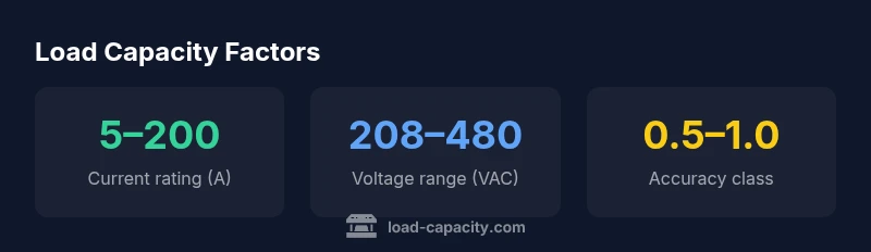
| Current rating | 5–200 A | Primary service ratings vary by model |
| Voltage class | 208–480 VAC | Line-to-line; region-dependent |
| CT/VT burden | <meter-specified limit> | Total burden includes wiring and meter input |
| CT ratios | 1:1 to ~600:5 | Depends on service size and scaling needs |
| Accuracy class | 0.5–1.0 | Depends on standard and installation |
Quick Answers
What determines a 3 phase meter's load capacity?
Load capacity is determined by current rating, voltage class, CT/VT configuration, and the total burden in the measurement chain. These factors together define the range over which the meter can measure power and energy accurately.
Capacity is set by current rating, voltage class, CT/VT setup, and burden. These determine the measurable, accurate range of power and energy.
Can I use a 3 phase meter for high-load industrial applications?
Yes, provided the meter’s ratings match the service conditions and CT ratios are configured correctly. For very high loads, ensure the primary rating and burden stay within specified limits and verify with commissioning tests.
Yes, if ratings and CT setup match the service and you test during commissioning.
What is CT/VT burden and why does it matter?
Burden is the impedance the CT/VT presents to the primary circuit. High burden reduces accuracy and can shift the meter’s response. Keep burden within the meter’s specified limits to maintain linear, accurate readings.
Burden is the impedance loading the CT/VT; too much burden lowers accuracy.
How do I verify load capacity in the field?
Check datasheets, perform commissioning tests at multiple load points, and compare results with calibrated references. Adjust CT ratios or burden if discrepancies appear until measurements align with standards.
Review datasheets, test at several loads, and verify against calibrated references.
What are common metering sizing mistakes?
Common mistakes include ignoring CT burden, mis-sizing voltage class, and failing to account for wiring losses. A system-wide model helps catch these issues during design.
Overlooking CT burden and wiring losses is a frequent error.
Which standards apply to meter load capacity?
Standards vary by region, but metering and electrical-safety best practices—verification of CT/VT, burden, and accuracy—are widely emphasized. Always reference local codes and IEC/IEEE guidance as applicable.
Follow local codes and IEC/IEEE guidelines for metering and safety.
“"Effective load-capacity planning ensures accurate metering across varying load profiles and environmental conditions."”
Top Takeaways
- Identify service voltage and peak current early
- Match CT/VT configuration to meter input range
- Keep total burden within meter specifications
- Verify sizing with field commissioning tests
- Document assumptions for ongoing maintenance