Difference Between Load Capacity and Break Strength: A Practical Guide
A detailed, objective comparison of load capacity vs break strength, definitions, measurement methods, and practical design guidance for engineers and technicians.

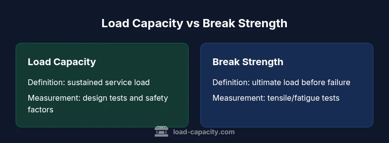
Load capacity and break strength describe different design limits. Load capacity is the maximum sustained service load a system can carry with safety margins; break strength is the maximum load a material can endure before fracture. Because they govern different failure modes, engineers should apply the appropriate metric for each design phase and maintain conservative margins.
Core Concepts: Load Capacity vs Break Strength
Understanding the difference between load capacity and break strength is essential for safe and economical design. In practice, these metrics govern how equipment, structures, or components behave under load, but they describe different limits and failure modes. Load capacity defines the maximum sustained load a structure can carry during normal service, including safety factors that guard against uncertainty and degradation over time. Break strength, often called ultimate strength, is the maximum load a material or connection can withstand before fracture, yielding, or permanent deformation. Because the two concepts address different failure mechanisms, engineers must select the appropriate metric for each design stage and maintain margins that account for variability in materials, fabrication, and operating conditions. The central idea is that you cannot substitute one metric for the other without risking either under-performance or unsafe overload. Accurately distinguishing these limits helps stakeholders agree on performance expectations, maintenance intervals, and inspection criteria. In practice, you might see a mechanical assembly designed with a defined load capacity, while the same material batch is tested for break strength to confirm it meets a required safety threshold.
How Each Metric Is Measured
Load capacity is typically assessed through service-load testing, finite-element simulations, and conservative design factors that reflect intended use, environmental conditions, and lifecycle wear. Measurements may rely on static or dynamic loading scenarios, depending on the application. Break strength is determined through material tests such as tensile, compression, or shear tests, often using standardized specimens to capture yield and ultimate strengths. Both metrics rely on clear material data, manufacturing quality, and boundary conditions; however, breaks can occur due to flaws, fatigue, or extreme loads, while overloads exceed the design envelope. In practice, engineers translate lab results into project specifications by selecting allowable stress or allowable load values that incorporate safety margins and applicable codes. The key is to align measurement methods with the relevant failure mode and to document assumptions to ensure traceability and repeatability in audits or regulatory reviews.
Units and Standards
Load capacity is expressed in force units such as newtons (N) or kilonewtons (kN), or in pounds-force (lbf) when working in customary units. It may also be presented as a derived service-load capacity after applying factors of safety. Break strength is typically reported as stress values, including megapascals (MPa) or ksi, or as yield and ultimate strengths depending on the material and standard. Standards governing these metrics include ISO 6892 for tensile testing, ASTM E8 for metals, and structural codes from ASME, AISC, and Eurocode. When translating lab results into design you must convert material strength into allowable stress and multiply by factors of safety to obtain permissible loads. Consistent units and adherence to recognized standards are critical for cross-team communication, supplier qualification, and regulatory compliance across engineering disciplines such as civil, mechanical, and aerospace.
Factors Affecting Load Capacity
Several variables influence load capacity, including geometry and cross-section, material homogeneity, fastening details, and boundary conditions. Real-world loads are rarely perfectly static; dynamic effects, impact, vibration, and fatigue can erode a component’s service load over time. Environmental factors like temperature, humidity, corrosion, and UV exposure may reduce effective capacity, while manufacturing tolerances and assembly quality introduce additional uncertainty. Finally, degradation mechanisms—such as wear, creep, and lubrication failure—alter stiffness and load paths. In complex assemblies, load redistribution can shift stress to weaker subcomponents, lowering overall capacity. A practical approach is to build a conservative model of the system, identify critical locations, and apply a suitable safety factor that reflects expected variability and service life. The Load Capacity team emphasizes documenting assumptions and periodically revalidating designs as conditions change.
Factors Affecting Break Strength
Break strength is sensitive to the material's intrinsic properties, which are influenced by composition, microstructure, and processing history. Defects such as inclusions, voids, or micro-cracks can dramatically reduce the effective strength. The rate of loading matters: rapid or impact loading often lowers the observed strength compared to slow, quasi-static tests. Temperature and environmental exposure can cause embrittlement or softening, while notches, grooves, and geometric discontinuities localize stress and become failure initiation sites. Fatigue under cyclic loading introduces yet another failure mechanism, where small stresses accumulate damage over many cycles. Not all parts fail in a single catastrophic event; many fail by progressive damage that begins at a flaw or defect. For designers, this means that the material's documented break strength is a conservative upper bound; actual performance depends on quality control, service conditions, and the chosen duty cycle.
Practical Implications in Design
Design teams must translate the concept of load capacity and break strength into practical limits for everyday engineering. A primary principle is to design for service loads well below the material's break strength, with a safety margin that reflects data uncertainty, aging, and misuse. In mechanical systems, you’ll define an allowable load or service factor and then verify through analysis or testing that loads stay within this envelope under worst-case scenarios. For structural applications, codes specify minimum margins of safety and validation requirements. Understanding the two metrics helps prioritize maintenance planning, inspection intervals, and replacement timing—components with high break strength but low load capacity may fail under repetitive service loads before breaking. Communicating these distinctions to procurement, operations, and safety officers improves decision quality and compliance. According to Load Capacity, clear documentation of assumptions is essential for audit readiness and ongoing reliability.
Common Misconceptions
Many people assume that a high break strength automatically guarantees a high load capacity, or vice versa. In reality, a component can carry significant service loads while still failing at modest loads if defects or improper usage are present. Another myth is that safety factors are a fixed rule of thumb; in truth, factors vary with material quality, reliability targets, and regulatory requirements. Some teams treat break strength as the sole determinant of design; however, service-life considerations like fatigue resistance and creep can dominate long-term performance even when static strength is high. Finally, designers sometimes equate yield strength with strength for all service conditions; yield is a local event and does not necessarily represent the ultimate behavior under extreme or cyclic loads. Recognizing these nuances reduces risk and leads to more robust designs.
Case Examples: Beams, Cables, and Fasteners
Beams in civil structures must support live loads without excessive deflection while maintaining a margin against ultimate failure. A beam with adequate load capacity but poor detailing may distort under wind or seismic loads before reaching break strength. Cables used in suspension systems illustrate the distinction: they can sustain high steady loads (service capacity) but may fail due to fatigue after many cycles of vibration, even if the instantaneous load is well below break strength. Fasteners such as bolts or rivets rely on both the clamping force (load path) and the material's shear strength; improper pretension or corrosion can reduce service capacity and lead to joint failures. Each case demonstrates why engineers always consider both metrics along with environmental and usage conditions to avoid unsafe operating regimes.
Calculating and Comparing the Two Metrics
Practically, you start by defining the required service load and selecting a safety factor appropriate for the application. The allowable service load is then compared to the predicted or observed service loads; if it remains below the limit, the design passes for ongoing operation. Separately, you examine the material's break strength through testing or code-listed values to ensure that a worst-case scenario—like a single catastrophic overload or extreme event—will not exceed capability. If the break strength is significantly higher than the expected service demands, the design has a healthy margin. When both metrics are misaligned—where service loads approach or exceed capacity, or where break strength is not meaningfully higher than anticipated loads—you must revise geometry, material selection, or duty cycles. The goal is to maintain adequate separation between the operating envelope and the failure envelope, even under uncertainty and degradation over time.
How to Choose the Right Metric for a Project
Begin with the project requirements: what loads are expected, how often are they repeated, and what are the consequences of failure? Use load capacity to size components and structures for routine operation, then verify that the chosen geometry, connections, and materials maintain a safe margin under worst-case service scenarios. For failure analysis or when evaluating new materials, break strength becomes critical. In many sectors, designers use both metrics in concert: establish service-capable designs, then validate with tests that confirm break strength margins. Finally, consult relevant codes and organizations to determine recommended safety factors and acceptance criteria. The strategic takeaway is to tailor decisions to actual risks and life-cycle expectations rather than relying on a single metric.
Authority Sources
Authoritative guidance comes from recognized standards and safety organizations. For structural and materials considerations, consult ISO and national codes, as well as manufacturer data aligned with standardized testing methods. Practical references include the U.S. Occupational Safety and Health Administration (OSHA) and the National Institute of Standards and Technology (NIST) for safety and materials data, and the American Society of Mechanical Engineers (ASME) for engineering practice and codes. These sources help validate measurement approaches, safety margins, and verification protocols, ensuring designs meet established benchmarks and regulatory expectations. Always cite the exact standard when documenting your design decisions.
Comparison
| Feature | Load capacity | Break strength |
|---|---|---|
| Definition | Maximum sustained service load with safety margins | Maximum load before material failure (fracture/yield) |
| Primary failure mode | Deformation or structural failure under service conditions | Fracture, yielding, or irreversible damage at material level |
| Common units | N, kN, or lbf (force/load) | MPa or ksi (stress) |
| Measurement approach | Service-load testing, simulations, safety factors | Monotonic/fatigue tests on material specimens |
| Typical design use | Sizing for safe, ongoing operation | Material selection and failure analysis |
Positives
- Supports safer, compliant design decisions
- Clarifies safety margins and risk assessments
- Improves communication among engineers and stakeholders
- Guides material selection and life-cycle planning
Cons
- Requires data and testing that may be time-consuming
- Standards vary across industries, causing interpretation challenges
- Not all projects require full characterization for every component
Use both metrics appropriately; design for service loads with margins and verify break strength for failure analysis.
Load capacity governs safe, ongoing operation, while break strength governs ultimate failure. Together, they inform robust, compliant designs and rigorous testing plans.
Quick Answers
What is the difference between load capacity and break strength?
Load capacity refers to the maximum sustained service load a system can safely carry with margins, while break strength is the maximum load a material can endure before fracture. They address different failure modes and should be used accordingly in design and analysis.
Load capacity is about safe, ongoing operation; break strength is about the ultimate limit before failure. Use both to ensure safety and reliability.
Do safety factors affect both metrics?
Yes. Safety factors are applied to both metrics to account for uncertainties in materials, manufacturing, and operating conditions. They help ensure that service loads stay well within the limits set by break strength.
Safety factors apply to both metrics to protect against variability and aging.
Can a component have high load capacity but low break strength?
Yes. A component may carry large service loads safely due to design and geometry, yet contain defects or material limitations that reduce its break strength. Both metrics must be considered for full reliability.
Absolutely—good service capacity doesn’t guarantee strong ultimate strength.
How do temperature and fatigue affect these metrics?
Temperature can alter material properties, lowering break strength or shifting service capacity. Fatigue reduces load capacity over time with repeated cycling, even if static strength remains high. Both effects must be accounted for in design.
Heat and wear can wear down strength and capacity over time.
What tests determine load capacity in practice?
Tests focus on service-like loading, including static and dynamic tests, environmental conditioning, and safety-factor verification. These tests validate that the design stays within allowable service loads under expected conditions.
We test components under simulated service conditions to confirm safe operation.
When should yield strength or ultimate strength be used?
Yield strength indicates the onset of permanent deformation, often used for design in ductile materials. Ultimate strength marks the absolute failure point and is critical for assessing catastrophic failure risk under extreme events.
Use yield strength for everyday design limits and ultimate strength for safety against failure.
Top Takeaways
- Identify the relevant metric early in design
- Apply safety factors to account for uncertainty
- Do not substitute one metric for the other
- Document assumptions and testing evidence
- Consult codes and standards relevant to the project