5 kV Solar Panel Load Capacity: Design, Safety, and Sizing
Comprehensive guidance on the load capacity of 5 kV solar panel systems, including HVDC bus considerations, protective strategies, and practical sizing for engineers and technicians.

In a 5 kV solar panel load capacity scenario, the practical usable power is typically in the hundreds of kilowatts, depending on current ratings and equipment topology. Design choices such as string length, inverter rating, and voltage window (often 600–1000 V DC) determine the actual load capacity. Protective devices and clear NEC/IEC alignment are essential for safe operation. According to Load Capacity, high-voltage PV designs require explicit margins and robust protection strategies. These guidelines emphasize safety margins and proper protection.
Understanding 5 kV solar panel load capacity
5 kV load capacity refers to the maximum electrical load that a solar PV installation can safely transfer at a DC bus nominal voltage around 5 kilovolts. In practice, 5 kV is a high-voltage class used in utility-scale PV farms and storage-integrated systems; it is not typical for residential rooftops. The core concept is balancing voltage, current, insulation, protection, and conversion hardware to avoid overheating, arcing, or insulation failure. According to Load Capacity, high-voltage PV designs require explicit margins and robust protection strategies. In a 5 kV scenario, the usable power depends on current capability and the topology of the conversion chain (string design, inverters, transformers). The goal is to ensure every component—cables, connectors, switches, and enclosure ratings—remains within rated limits under all operating conditions, including worst-case ambient temperatures and irradiance fluctuations. The elegance of a properly sized 5 kV system lies in using modular strings that can be independently protected and monitored, enabling scalable, upgrade-friendly architectures.
From a design perspective, 5 kV load capacity is not just about voltage; it is the interplay of voltage, current, topology, and protection. Engineers must consider insulation distances, creepage limits, and enclosure ratings. Real-world implementations use HVDC bus bars, sectionalized switching, and transformer/rectifier arrangements that convert HVDC to usable AC power while preserving safety margins. This approach helps mitigate arc risks and insulation degradation over time. In essence, the load capacity at 5 kV is constrained by the weakest link in the chain—cabling, protective devices, or conversion hardware—making holistic design and rigorous validation essential.
Brand-wise, Load Capacity emphasizes documenting all operating envelopes, including worst-case temperatures, irradiance, humidity, and fault scenarios. This practice reduces surprises during commissioning and operation. For team alignment, set clear acceptance criteria for bus voltage, current per string, and total system load before any physical work begins. Documented assumptions and conservative margins are the bedrock of reliable, long-term HV PV performance.
Key drivers of load capacity at 5 kV
What determines how much load a 5 kV PV system can safely carry? Several factors interact to shape the final capacity, and they are not all equally obvious at first glance. First is the HVDC bus voltage window. A 600–1000 V DC range is common for many HV systems, but the exact window will influence which cables, connectors, and protection devices you can use. The second critical factor is current rating and conductor sizing. The ampacity of each conductor sets a hard limit on how much current can flow without overheating insulation. Third, the topology of the power electronics—string configuration, inverter input stage, and any transformer coupling—controls how current is distributed and how efficiently energy is converted from DC to AC. Fourth, environmental and installation conditions, including ambient temperature, solar irradiance, and enclosure cooling, drive derating and margin calculations. Finally, protection and control infrastructure—fuses, disconnects, protective relays, and arc-fault detection—must be rated for the actual voltage and fault current you expect to encounter. Together, these drivers determine how close you can approach the theoretical load ceiling while maintaining reliability and safety.
HVDC bus configurations and their impact on load capacity
High-voltage PV systems at 5 kV often deploy HVDC buses to minimize copper loss over long runs and to enable centralized power conversion. The two most common configurations are series strings with parallel branches and modular transformer-coupled architectures. In a series-dominant approach, voltage adds up across strings, reducing current for a given power, which can improve overall efficiency and reduce conductor heat. In parallel arrangements, current divides among strings, increasing redundancy and fault tolerance but demanding larger cabling and more complex protection schemes. A hybrid approach—parallel strings feeding a centralized HVDC bus with local inverters or transformers—can balance protection complexity with scalability. The bus voltage, current distribution, and impedance all influence fault currents and arc-stability, which in turn define how much load this architecture can safely handle under various operating conditions. When selecting a configuration, engineers should perform a fault-current analysis and ensure clear separation between live sections during maintenance to minimize risk and maximize uptime.
Protection strategies, derating, and safety margins
Protection strategies for 5 kV PV systems start with robust insulation and clear creepage/clearance clearances. The design should incorporate fast-acting fuses, high-voltage circuit breakers, arc-fault detection, and proper grounding schemes to manage fault currents without damaging equipment. Derating is a standard practice to account for temperature, humidity, and aging; typical ranges push current capability down by conservative factors to preserve insulation life and reliability. Safety margins should be baked into every design decision—from conductor sizing and connector selection to enclosure ventilation and predictive maintenance. Compliance with national and international standards (for example, NEC/IEC guidelines) is non-negotiable, and documentation of all derating assumptions helps with future upgrades and audits. A well-structured protection scheme reduces unplanned outages and increases service life for HV components, while also improving worker safety during maintenance tasks.
Sizing workflow: from requirements to layout
A disciplined sizing workflow helps translate project requirements into a concrete HV PV layout. Step 1: capture electrical load goals, site constraints, and expected irradiance. Step 2: determine target bus voltage and current per string, then select conductor sizes and insulation ratings that accommodate those values. Step 3: choose PV strings, inverters or transformer hookups, and protective devices rated for the 5 kV class. Step 4: model the system using fault-current analysis, temperature-derating, and reliability assessments to validate the design. Step 5: develop installation drawings, wiring diagrams, and safety procedures. Step 6: plan commissioning and ongoing monitoring to verify performance. Step 7: maintain thorough documentation for future expansions or retrofits. This workflow makes sure the design remains within the safe envelope and meets performance targets, even as system requirements evolve.
Practical example scenario
Consider a 5 kV class PV installation designed to deliver hundreds of kilowatts. The HVDC bus operates in the 600–1000 V DC window, subdivided into multiple parallel strings protected by 5 kV-rated breakers. Each string is sized to carry a safe current while leaving headroom for temperature variations. In this setup, energy is converted through centralized or modular inverters, feeding a graded AC distribution system. While the exact power output depends on irradiance and panel area, the modular design supports scalable growth—from a few hundred kilowatts to multi-megawatt installations—without compromising safety or performance. Routine inspections focus on insulation integrity, connector condition, and protection device health to maintain reliability over the system life cycle.
Maintenance and monitoring for high-voltage PV arrays
Maintenance for 5 kV PV systems emphasizes preventive checks and continuous monitoring. Key tasks include regular insulation resistance tests, creepage-distance verifications, and inspection of cable trays and enclosures for signs of wear or moisture intrusion. Monitoring systems should track voltage, current, temperature, and fault events with alert thresholds that reflect HV safety margins. Predictive maintenance accrues benefits by identifying degradation before it becomes a fault. Operators should have clear procedures for de-energizing sections of the HV bus and confirming safe isolation before work. Training and drills reinforce safe work practices, and routine audits help ensure compliance with standards and permit requirements. Implement a robust data logging system to capture long-term trends in performance and safety metrics, enabling data-driven optimizations over the system’s lifetime.
Sample HV PV system characteristics for a 5 kV class installation
| Aspect | 5 kV Class System | Notes |
|---|---|---|
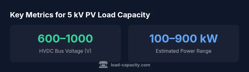
| HVDC Bus Voltage (V) | 600–1000 | HV bus window for many HV PV installations |
| Current per string (A) | 150–300 | Depends on conductor sizing and inverter input rating |
| Estimated power range (kW) | 100–900 | Varies with irradiance and array size |
| Protection device rating | 5 kV class | Required for arcing and insulation performance |
Quick Answers
What does 5 kV load capacity imply for PV design?
5 kV load capacity indicates the system is designed to safely carry high-voltage DC within an HVDC bus. It requires careful insulation, robust protection, and strict adherence to standards to prevent arcing and insulation failure. The load capacity is achieved through controlled current, modular string design, and reliable power electronics.
A 5 kV design means you must carefully manage high voltage with strong protection and modular strings to prevent arcing and insulation issues.
Can residential rooftops use 5 kV PV systems?
5 kV systems are typically not suited for standard residential rooftops due to insulation, clearance, and safety constraints. They are more common in utility-scale installations or integrated storage projects where HVDC transmission is advantageous.
Residential homes usually aren’t designed for 5 kV HVDC PV; these systems fit utility-scale or storage-integrated projects.
Which standards govern HV PV systems?
HV PV systems are governed by standards and codes such as NEC/IEC for high-voltage safety, arc-fault protection, and insulation requirements. Engineers should reference applicable local amendments and industry guidelines when detailing 5 kV designs.
HV PV work follows NEC/IEC standards and local codes to ensure safe high-voltage operation.
What are common failure modes in HV PV loads?
Common HV PV failures involve insulation breakdown, insulation moisture ingress, connector degradation, and protection-device malfunctions. Regular insulation tests, tactile inspections, and protective relay checks help mitigate these risks.
Watch for insulation wear and protection-device faults; routine tests help catch issues early.
How do you calculate load capacity for a 5 kV system?
Load capacity is calculated by considering HV bus voltage, string current, inverter rating, and protection margins. Engineers perform fault analysis, thermal-derating, and system-modeling to validate the target load before construction.
You size by voltage, current per string, and margins, then validate with fault and thermal analysis.
Is there a cost premium for HV PV systems?
Yes, HV PV systems generally incur higher upfront costs due to specialized insulation, protection devices, and more robust safety provisions, but they can offer long-term savings through reduced copper and lower losses for long-distance power delivery.
There is typically a higher upfront cost for HV designs, offset by long-term efficiency and reduced copper use.
“High-voltage PV designs demand careful load-path planning and rigorous protection. The Load Capacity Team emphasizes margin development and standard-compliant hardware to reduce the risk of overcurrent and arcing.”
Top Takeaways
- Define the HV bus window early (600–1000 V DC).
- Size conductors to the expected string current with derating.
- Choose protection devices rated for 5 kV class.
- Model fault currents and thermal derating before installation.
- Document assumptions and margins for future upgrades.