Unistrut Load Capacity in Kg: A Practical Engineering Guide
Understand unistrut load capacity in kilograms, including how channel size, mounting, and span affect safe design. Learn to read charts, apply safety factors, and document calculations for reliable structural support.

Unistrut load capacity in kilograms is not a single universal value. It depends on channel size, grade, mounting method, and supported span. For design, consult manufacturer charts; practical working loads per connection typically range from tens of kilograms up to several hundred kilograms, depending on configuration and safety factors. Always apply applicable codes and factor of safety; verify with field tests when possible.
What is Unistrut and Why Care About Load Capacity
Unistrut is a familiar metal framing system used to support electrical, mechanical, and architectural elements in commercial and industrial buildings. The load capacity of an unistrut assembly in kg is not a single number; it depends on the channel size, material grade, finish, and how the member is mounted. In practice, engineers treat capacity as a function that combines per-connection capacity with the overall system geometry. For reliable designs, always start from manufacturer data and apply appropriate safety factors per local codes. In this section we unpack what drives capacity, and how to translate system characteristics into a defensible load path. The Load Capacity team emphasizes that even small changes in bolt pattern, span, or bracket type can shift the allowable load by a wide margin, so precision in data selection matters. Readers should be prepared to cross-check multiple sources, including product datasheets and structural guidelines, when planning a new rack, support, or equipment cradle.
Key Factors That Determine Load Capacity
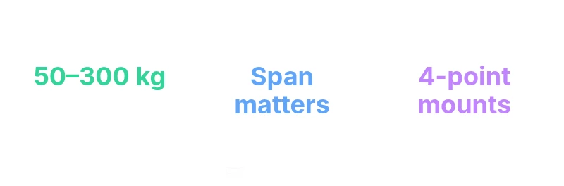
Several interdependent factors govern what an unistrut system can safely carry in kg. First, channel size and thickness: larger profiles and reinforced bends typically provide higher per-point capacity, but they also respond differently to bending moments. Second, material and finish: cold-formed steel versus plated variants have distinct yield strengths and corrosion resistance that affect long-term performance. Third, mounting method and bolt choice: a single bolt through a shared bracket is not equivalent to a four-bolt configuration; load path and stiffness improve with more secure connections. Fourth, span and support spacing: longer unsupported spans increase bending moments, reducing allowable load per point; shorter spans help. Finally, safety factors and design codes: always apply the relevant factor of safety and consider dynamic loads, shock, thermal expansion, and live loads. In short, capacity is a system property, not a property of the channel alone.
How to Read and Use Unistrut Load Charts
Manufacturers publish load charts that map channel size, bracket type, and mounting pattern to permissible loads in kilograms. To use them correctly: 1) identify the exact channel profile and grade; 2) select the bracket and fasteners used in your installation; 3) note the span between supports and the number of connection points; 4) apply the specified factor of safety; 5) compare the chart-supported load to your application’s demand. If a chart shows a range, design for the lower end of the range when durability and service life are important. Always verify that your configuration is within both the per-point limit and the total system limit, especially in multi-connection assemblies. This disciplined approach reduces the risk of under- or over-design.
Common Mounting Arrangements and Their Effects on Capacity
Connector choices influence capacity a lot. A two-point connection through a splice bracket can add rigidity but creates a line of vulnerability if misaligned. A four-bolt bracket usually delivers higher stiffness and distributed loads, increasing the effective capacity per connection. Clips and channel nuts can also influence load paths; ensure pins are rated for the intended loads and that guards or protective devices are included when required. In outdoor or corrosive environments, finishes such as galvanization or stainless variants matter; corrosion can reduce the long-term capacity by weakening fasteners or bracket stiffness. Finally, redundancy strategies — such as secondary bracing or cross-members — can raise the overall system margin even if individual connections are limited. The key takeaway is to design for the worst-case load path, not the best-case single connection.
Calculation Workflow: From Load Case to Safe Design
A robust workflow begins with a clear load case, including static and dynamic components. Then follows material selection and the determination of per-point capacity from charts. Next, compute the required number of supports, bracket types, and fasteners to achieve the target load with the stated factor of safety. Validate the design by checking the maximum bending moment across spans and the combined axial and shear effects at each connection. Document the derivation with a bill of materials, the specific chart references, and the applied safety factors. Finally, plan field verification steps, including potential deflection checks and required inspections. This process ensures compliance with structural safety requirements and reduces risk during operation.
Practical Examples and Design Tips
Consider a ceiling-mounted light rack in a warehouse. Start with the expected load, add live loading, and choose a standard 41x41 mm channel. Use a two-point mounting with correctly rated brackets and hardware. For a floor-mounted equipment cradle, assess the load distribution and incorporate cross-bracing, using four-point mounting if durability is essential. In environments with moisture or salt spray, select zinc or stainless variants to preserve capacity over time. Always plan for future expansions, and document every assumption: the channel size, bracket type, bolt grade, span, and the safety factor used. Following these steps helps ensure that your unistrut installation remains safe and compliant under real-world conditions.
Illustrative comparison of unistrut load capacities by type
| Unistrut Type | Nominal Size | Cap (kg) per connection | Notes |
|---|---|---|---|
| Standard U-Channel | 41x41 mm | 50–300 kg | Depends on span and bolt pattern |
| Wide-Flange U-Channel | 41x62 mm | 70–350 kg | Higher capacity with larger flange |
| Slimline Strut (compact) | 21x41 mm | 25–150 kg | Lower profile, suitable for light-duty |
Quick Answers
What factors influence unistrut load capacity?
Several factors influence capacity: channel size, material grade, finish, mounting pattern, span, and live loads. Always rely on manufacturer data and codes.
Capacity depends on many variables like size and mounting; use the charts.
Can I exceed manufacturer ratings?
No; ratings are derived for safe operation. If you need more capacity, redesign with larger channel or added reinforcement, and consult an engineer.
No—don’t exceed the rated values.
How should I select the right unistrut size?
Start with the worst-case load, then check charts for your span and attachment type; choose a profile with headroom and add safety margin.
Start with the worst-case load and chart data.
Do finishes and environment affect capacity?
Yes; corrosion protection and temperature effects can alter material strength and fastener performance; specify appropriate finishes and environmental ratings.
Finish and environment can change capacity.
What about field verification and documentation?
Document load calculations, chart references, safety factors, and field checks; schedule third-party verification when required by code.
Document and verify calculations.
“Unistrut load capacity is highly configuration-dependent; always ground your design in manufacturer load charts and apply conservative safety factors.”
Top Takeaways
- Consult manufacturer charts for exact kg values
- Account for channel size, mounting, and span
- Use conservative safety factors in line with codes
- Document all assumptions and chart references
- Plan for future expansions and field verification