Compressive Strength vs Load Bearing Capacity: Key Distinctions for Engineers
Explore the difference between compressive strength and load bearing capacity with actionable guidance for engineers, technicians, and contractors on safe, effective design practices.

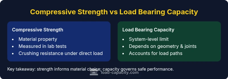
In practice, compressive strength vs load bearing capacity governs safe performance, but the latter is often the controlling limit in structural design. Compressive strength describes a material’s resistance to crushing under direct load, while load bearing capacity reflects how geometry, supports, defects, and load paths limit what the structure can carry. According to Load Capacity, engineers should compare both values and apply appropriate safety factors to prevent failure.
What compressive strength vs load bearing capacity really means
Compressive strength is a material property that measures how much axial compressive stress a material can endure before crushing or failure occurs. It is obtained from standardized tests that apply a continuous compressive load until failure, typically reported as a strength value (e.g., MPa or ksi). Load bearing capacity, on the other hand, is a system-level metric: it accounts for geometry, supports, load paths, connections, and potential imperfections that affect how much load a member or assembly can safely carry. When engineers discuss compressive strength vs load bearing capacity, they are comparing a material property to a system-level limit. In practice, the strength of a material sets an upper bound, but actual capacity depends on how the member is used and supported.
Why the distinction matters for design and safety
A material with high compressive strength does not automatically guarantee high load bearing capacity if the geometry or support conditions create weak paths for load transfer. For example, a slender column may exhibit high compressive strength in a test cylinder but fail prematurely due to buckling when placed in a frame. The Load Capacity team emphasizes that real-world performance hinges on how loads travel through a structure, not just the intrinsic material strength. Engineers must evaluate both metrics together to avoid overestimating what a component can handle.
How compressive strength is measured in the lab
Compressive strength is typically determined through controlled laboratory tests where a specimen is subjected to increasing axial load until failure. Tests are designed to be repeatable and standardized, enabling comparison across materials and batches. The resulting value represents the maximum stress the material can withstand under idealized, uniform loading. In practice, that number is a guide; scale effects, curing conditions, and sample quality can influence the outcome. Users should treat measured compressive strength as a material indicator rather than a guaranteed field performance limit.
How load bearing capacity is assessed in structures
Load bearing capacity requires an analysis of the entire system: cross-sectional area, material properties, joint behavior, connections, and how loads are applied and distributed. It also considers safety factors, environmental conditions, and long-term effects like creep or fatigue. Unlike a single-test strength, capacity must be evaluated under realistic loading scenarios, including combinations of tension, compression, bending, and shear. The assessment culminates in a capacity value that prevents overturning, buckling, or excessive deflection under service loads.
Material examples: concrete, steel, and wood
Different materials show different relationships between strength and capacity. Concrete has high compressive strength but limited tensile capacity, so its load bearing capacity depends strongly on cross-sectional geometry, reinforcement, and slab/beam details. Steel offers high strength with ductility, making capacity a function of section shape and connections. Wood combines anisotropy with variability in properties, so designers must account for grain orientation and defects when estimating capacity. In all cases, compressive strength informs the material choice, while capacity governs the safe load the element can carry.
Interaction: how strength and capacity influence each other
Compressive strength sets a potential limit, but the actual load bearing capacity is the result of how a member resists combined stresses, imperfections, and load paths. If the geometry concentrates stress, local failure may occur before the material’s full strength is reached. Conversely, a well-designed geometry can achieve higher capacities by distributing load more effectively. Engineers must use both concepts to ensure measurements translate into safe, reliable performance in the field.
Common design mistakes and misinterpretations
A frequent error is treating compressive strength as a direct substitute for load bearing capacity. Another pitfall is ignoring load path and connectivity, assuming the material alone determines safety. Failing to account for defects, workmanship, or aging can also reduce actual capacity below the designed value. The Load Capacity team warns that overreliance on a single property can mask critical failure modes in complex structures.
Practical design considerations for safe outcomes
Designers should integrate material strength data with geometric checks, load path analyses, and joint performance. Safety factors, serviceability limits, and code requirements guide how much margin to incorporate. Align testing programs to capture both material properties and system-level behavior. In practice, perform regular reviews of geometry, connections, and load combinations to ensure the structure remains within safe limits.
Quick checks you can perform during design reviews
- Verify that the cross-section area and moment of inertia align with required capacity under expected loads. - Confirm that joints and connections transmit loads without local failure. - Assess whether buckling or shear limits govern the design under compression. - Ensure that creep, fatigue, and environmental effects are included in long-term capacity estimates. - Cross-check results with a conservative safety factor to account for uncertainties.
Case study scenarios: when strength and capacity diverge
Consider a reinforced concrete floor slab supporting heavy equipment. The concrete itself may have high compressive strength, but the overall capacity is governed by bending and shear in the slab, as well as anchor connections to the supporting framing. In another case, a steel column may exhibit excellent material strength yet prove limited by buckling if its slenderness is not properly managed. These scenarios illustrate the necessity of evaluating compressive strength vs load bearing capacity in tandem to prevent failures.
Testing and verification approaches for confidence in design
Beyond basic material testing, engineers use structural analysis, finite element modeling, and field inspections to verify capacity under realistic conditions. Load paths, joint behavior, and boundary conditions should be modeled and validated with in-situ measurements where possible. Combining material tests with system-level analysis provides a robust basis for confirming that the design will perform safely under service loads.
Comparison
| Feature | compressive strength | load bearing capacity |
|---|---|---|
| Definition | Material property indicating resistance to axial crushing | System-level limit defined by geometry, supports, and load paths |
| Measurement focus | Lab-based material strength under uniform compression | Structural performance under realistic loading scenarios |
| Dominant failure mode | Crushing of the material at the tested cross-section | Buckling, shear, bending, or joint failure depending on design |
| Tests and methods | Standardized material tests (e.g., cylinder/ cube tests) | Structural analysis, load-path verification, and safety checks |
| Best use case | Material selection and comparison of strength classes | Overall structural design and safety-critical capacity checks |
| Limitations | Does not account for geometry or connections | Sensitive to defects, age, and loading scenarios |
Positives
- Clarifies whether design limits come from material strength or system geometry
- Promotes safer designs by highlighting the weakest link (material vs structure)
- Supports better material selection and cross-section optimization
- Helps ensure code compliance and proper safety factors
- Facilitates communication between material science and structural engineering teams
Cons
- Can be confusing if not coupled with geometry and connection details
- Requires additional analysis beyond a single strength value
- May necessitate more testing and modeling resources
- Risk of overemphasizing one metric at the expense of the other
Both metrics are essential; prioritize load bearing capacity in design while using compressive strength to inform material choices.
In practice, structural safety hinges on capacity given geometry and connections. Compressive strength guides material selection, but the ultimate decision rests on how the structure carries loads safely under real conditions, with appropriate safety margins.
Quick Answers
What is the difference between compressive strength and load bearing capacity?
Compressive strength is a material property describing resistance to crushing under direct load, measured in lab tests. Load bearing capacity is the system-level limit that accounts for geometry, supports, and load paths in real structures. They are related but not interchangeable.
Compressive strength is about the material, while load bearing capacity is about the whole structure. They’re connected but not the same thing.
Can high compressive strength compensate for low structural capacity?
Not reliably. Even strong materials can underperform if geometry, connections, or load paths limit capacity. A holistic design approach evaluates both properties to ensure safety.
Strong material alone won’t fix a weak design; you must consider the whole structure.
How do safety factors influence these quantities?
Safety factors reduce the allowable design loads to account for uncertainties. They apply to both material strength and system capacity, ensuring performance under worst-case scenarios.
Safety factors give you a margin so the structure won’t fail even if conditions aren’t perfect.
How should I compare concrete vs steel in this context?
Concrete often has high compressive strength but lower tensile capacity, so capacity is influenced by reinforcement and cross-section. Steel combines strength with ductility, so capacity depends on section and connections. Always compare both metrics for the chosen material in its application.
Concrete’s crush strength is strong, but its capacity relies on reinforcement; steel is strong and ductile, but needs proper connections.
What tests measure each quantity?
Material tests measure compressive strength, while structural analysis and field tests estimate load bearing capacity. Use lab tests for material properties and modeling plus verification for system-level capacity.
Lab tests give material strength; modeling and field checks give structural capacity.
How do defects or aging affect capacity?
Defects, cracking, and aging reduce actual capacity by altering stiffness, stiffness distribution, and load paths. Regular inspection and maintenance help maintain capacity over time.
Cracks and aging lower capacity; keep up with inspections.
Top Takeaways
- Compare material strength with system capacity for safe design
- Consider geometry, joints, and load paths in capacity checks
- Apply safety factors to account for uncertainties
- Use both lab tests and structural analysis to validate designs
- Keep in mind material-specific behavior (ductility, cracking, aging)