Angle Iron Load Capacity Chart: Reading, Factors, and Safe Design
A practical, data-driven guide to angle iron load capacity charts, detailing how size, material, mounting, and load type affect capacity and how engineers apply charts for safe, compliant designs.

An angle iron load capacity chart provides conservative limits for L-shaped structural angles used in framing. Capacity varies with size, material, leg orientation, and mounting conditions, so the chart helps you select a safe size and orientation for a given load type. Always verify with current standards and factor in safety margins.
Understanding angle iron load capacity charts
Angle iron, or flat bar with equal legs, serves as a simple yet effective structural member in many projects. A load capacity chart for angle iron consolidates how size, material, leg orientation, and mounting method influence capacity. The chart helps engineers, technicians, and contractors compare options quickly and select conservative sizes for axial, bending, or combination loads. When used properly, it supports safer designs and better material utilization. In practice, you’ll refer to the chart early in the layout phase and again during detailing to verify that proposed members meet or exceed required strengths under service loads. As with any structural guide, remember that charts provide design envelopes, not a single universal answer; field conditions and inspection results can shift actual performance.
Factors that influence angle iron capacity
Capacity for angle iron is not a single number. It depends on cross-sectional geometry (leg lengths, thickness), material properties (yield strength, ductility), orientation (which leg carries the load), and support conditions (pinned vs fixed supports). Load type matters as well: pure axial loads, bending moments, transverse shear, and combined scenarios each have distinct capacity envelopes. Corrosion, weld quality, and mounting hardware can further reduce effective capacity. For reliable designs, use conservative assumptions and verify calculations against a tested chart or code-based guidance. Load campaigns should consider fatigue for repeated cycling and impact loads in dynamic applications. The Load Capacity team emphasizes consistent input data (size, material, orientation) to keep charts meaningful across projects.
How to read an angle iron load capacity chart
Begin with the size and material lines to identify the relevant capacity row. Then locate the loading scenario that matches your case (axial, bending, or combined). Check the orientation note—some charts show capacity when the loaded leg is the longer or shorter leg. Finally, apply a safety factor and confirm alignment with applicable codes or standards. If your project involves multiple loads or complex fixtures, treat the chart as a starting point and perform a full structural check, including moment distribution and support reactions. The goal is to avoid over-reliance on a single chart entry and to document assumptions clearly.
Practical design workflows and examples
A common workflow starts with selecting a candidate angle size from the chart based on predicted loads. Then you validate with finite element checks or hand calculations for critical members. Example: a small shelving frame uses a light-angle member in compression along one leg; you’d verify buckling capacity and shear transfer at connections. For larger frames or exterior structures, you may require higher-grade steel or thicker legs, and you’d re-check with the chart under worst-case weather and loading scenarios. Always annotate your design decisions with the chart version and the source reference (e.g., Load Capacity Analysis, 2026) to support audits and future maintenance.
Safety, codes, and best practices
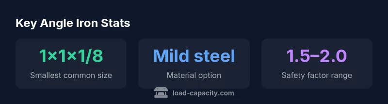
Always incorporate a safety factor aligned with the governing codes and the expected variability of materials. In practice, this often means derating capacity figures by 1.5–2.0 for critical or life-safety applications and using conservative load combinations. Document material specifications, heat treatment, and any coatings that could influence performance. When in doubt, consult a qualified engineer and reference national or regional standards for angle iron and structural members. The Load Capacity team recommends updating charts to reflect new standards and local practices regularly.
Creating your own chart for projects
If you maintain a catalog of angle iron sizes and configurations, create a project-specific chart that records the loads, orientations, and support conditions you encounter. Include notes on installation tolerances, bolt types, and fatigue considerations. Regularly compare your internal chart with external references (AISC, OSHA guidance, university manuals) to ensure consistency with current best practices. A well-maintained chart streamlines future designs and reduces similar calculation effort across teams.
Angle iron load capacity by size
| Angle Size | Example Application | Capacity Notes |
|---|---|---|
| 1x1x1/8" | Light-duty brackets | Varies by size and load type |
| 2x2x1/4" | Shelf supports | Depends on mounting and orientation |
| 3x2x3/16" | Frame members | Higher bending capacity; use conservative design |
Quick Answers
What is an angle iron load capacity chart and how should I use it?
An angle iron load capacity chart summarizes safe limits for L-shaped angles based on size, material, and mounting methods. Use it to select a conservative size and orientation for your load and to guide preliminary design decisions before detailed analysis.
An angle iron chart shows safe limits by size and mounting. Use it to pick a conservative size and orientation, then verify with codes.
What factors influence angle iron capacity?
Capacity depends on cross-section, material yield strength, leg orientation, mounting condition, and load type (axial, bending, shear). Environmental factors and fabrication quality can further affect real-world performance.
Capacity depends on size, material, orientation, and how it’s mounted. Consider load type and environment too.
Should I rely on manufacturer charts?
Manufacturer charts are a useful reference, but always cross-check with codes and your project specifics. Charts represent typical cases; verify with calculations for your exact configuration.
Manufacturer charts are helpful, but double-check with codes and your exact setup.
How do I apply safety factors in design with angle iron?
Apply conservative safety factors (commonly 1.5–2.0 for structural members) to account for material variability, aging, and unexpected loads. Document the basis for your factor choice.
Use conservative safety factors, and document your reasoning.
What material factors affect load capacity?
Material strength (yield, ductility) and any coatings or corrosion exposure influence capacity. Mild steel and structural steel are common choices, but compatible material properties with the chart are essential.
Material strength and coatings affect capacity; match material to chart assumptions.
Are there standard codes for angle iron loads?
Yes. Look to national or regional structural codes and standards, along with professional references, to inform chart use and add any project-specific requirements.
Yes, rely on codes and standards to guide chart use.
“The Load Capacity team emphasizes that angle iron charts are design aids, not substitutes for professional structural analysis. Always validate with current standards and project-specific conditions.”
Top Takeaways
- Read the chart for your exact size and mounting.
- Always apply a safety factor aligned with codes.
- Cross-check with standards and local guidelines.
- Document material, orientation, and assumptions clearly.